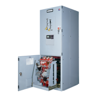
Data Form -RPTCS Automatic Transfer Switch
Low Voltage
Customer Job No.
Address Date
Customer Device ID
Equip. Loc. Ambient (if avail.) °F Humidity %
Model No. Ser. No. Voltage
Cntrl Ser. No. Cntrl Type Ampacity
37968-1A/B
MMHA14000284 RPTCS-01
480.00 V
225 A
St Josephs Hospital
350 W.Thomas Rd, Phoenix. AZ
Parking garage
37968-1A/B
1/9/2015
RTS03-ABOB2254AMF1
BYPASS
ar
up:
reven
a
ve
a
n
:
ATS Ship Date: Startup Date: Last Maintenance:
3.2 Pre-Energized Safety Checks
X 3.2.1 Hi-pot or megohm performed and/or report attached. X 3.2.3 Circuits have been cleared to be energized.
X 3.2.2 Lockout/tagout procedures reviewed. X 3.2.4 Area has limited access to authorized personnel only.
3.3 Equipment Safety
X 3.3.1 Equipment is properly grounded. N/A 3.3.3 Source breaker(s) is wired for shunt trip on closed transition.
332S b k t t d d t di ti t d
11/20/2014 1/9/2015
.
.
ource
rea
ers
es
e
an
se
per coor
na
on s
u
y.
5.1 System/De-Energized Inspection
X 5.1.1 Shipping or installation damage and foreign debris. X 5.1.4 Interlock rod operation.
X 5.1.2 Screw tightness and wire pull checks. X 5.1.5 Power and ground connections for proper tightness.
X 5.1.3 Interconnects are wired properly. X 5.1.6 Tightness checks; bus, components, structure.
5.1.7 or 5.1.8 Bypass Switch Inspection (if applicable) Legend
X Bypass handle operation. X Isolation handle operation. X Completed
XFin
er cluster ali
nment. X Interlock rod o
eration. N/A Non A
licable
X Secondary contact inspection. X Isolation mechanism. SN See Notes
5.2 Settings/Readings Additional Settings Printout Attached?
5.2.2 Pickup/Dropout Settings
S1= S2=
Under Voltage Fail Under Voltage Fail
Under Voltage Restore Under Voltage Restore
Under Frequecy Fail Under Frequecy Fail
90%
80%
90%
56.0 Hz
80%
90%
56.0 Hz
80%
90%
56.0 Hz
80%
90%
56.0 Hz
80%
90%
56.0 Hz
As Found SpecifiedAs Found Specified As Left
Utility Generator
As Left
80%
56.0 Hz
n
er
requecy
es
ore
n
er
requecy
es
ore
Over Voltage Fail Overr Voltage Fail
Over Voltage Restore Over Voltage Restore
Over Frequecy Fail Over Frequecy Fail
Over Frequecy Restore Over Frequecy Restore
5.2.3 Timers Readings
Delay for Generator Start 5.4.1.24 Battery Voltage
Delay - Xfer to Nonpreferred Src Vab 487 V 487 V 487 V
As Left
00:00:00
00:00:02
00:00:00
As Found Specified
00:00:02
00:00:00
69.8 Hz
66.0 Hz
.
z
00:00:02
108%108%
69.8 Hz
66.0 Hz
.
z
110%
108%
69.8 Hz
66.0 Hz
.
z
110%
108%
S1
110%
108%
69.8 Hz
66.0 Hz
.
z
110%
108%
69.8 Hz
.
z
69.8 Hz
66.0 Hz 66.0 Hz
110%
S2
.
z
110%
TDES
TDNPS
Delay - Xfer to Preferred Source Vcb
Delay - Center off to Non-Preferred Vca
Delay Center off to Preferred Frequency
Delay for Engine Cooldown Phase Rotation
Delay for Generator Sag. Vab
Preferred Sag. Timer Vcb
Preload Control 1 Timer Vca
Post Load Control 1 Timer Frequency
S2
0 V
0 V
0.00 Hz 0.00 Hz
0 V
0 V
0 V
0.00 Hz
0 V
0 V
0 V
ABC
488 V 488 V
ABC
488 V00:03:00
S1
00:03:00 00:03:00
00:00:00 00:00:00
00:05:00 00:05:00
00:00:00
00:00:00 00:00:00
00:05:00
489 V 489 V
00:00:00
489 V
0 V
ABC
TDTO
TDPS
TDNNP
TDNPS
TDEC
Fail to Sync Timer Phase Rotation
5.3 Operational Tests
5.3.1 Preferred Source Energized. Preferred Source Voltage Sensing.
5.3.2 Non-Preferred Source Energized. Engine Start Sequence.
5.3.3 Preferred and Non-Preferred Sources Energized. Non-Preferred Source Voltage Sensing.
5.3.3.4 Load Test. Automatic Transfer Operation.
5.3.3.5 Simulate Loss of Preferred Source. Engine Cooldown and Shutdown (TDEC).
5336ReturntoPreferredSource
Time Delay upon transfer to Preferred Source (TDNPS)
- - - - - - 180 s 180 s 180 s
.
.
.
.
.
5.3.3.7 Simulate loss of Non-Preferred Source. 5.3.4 Fail to Transfer Testing
5.3.3.8 Verify Load Control Operation. Other (Describe in Comments)
Form 90F1230001 rev B 2/29/2012
Page 1 of 2
 Loading...