13
Tubing
4.0 INSTALLATION
4.4.2.5 Capacity Losses
Long line lengths can result in a reduction in capacity
due to vapor line pressure drop and heat gain or loss.
Refer to Table 2 for capacity loss multipliers for various
vapor line diameters and equipment line lengths. This
table does not account for any capacity loss due to heat
gain or loss from the environment. It is extremely im-
portant not to oversize the vapor line to minimize capac-
ity loss at the expense of proper oil return. If the table
shows an “NR” for a particular vapor line diameter and
length, or, if a vapor line diameter is not listed, oil return
will not be adequate.
Table 1
Refrigerant tubing is measured in terms of actual length
and equivalent length. Actual length is used for refrig-
erant charge applications. Equivalent length takes into
account pressure losses from tubing length, ttings, ver-
tical separation, accessories, and lter driers. The table
below references different commonly used equivalent
lengths.
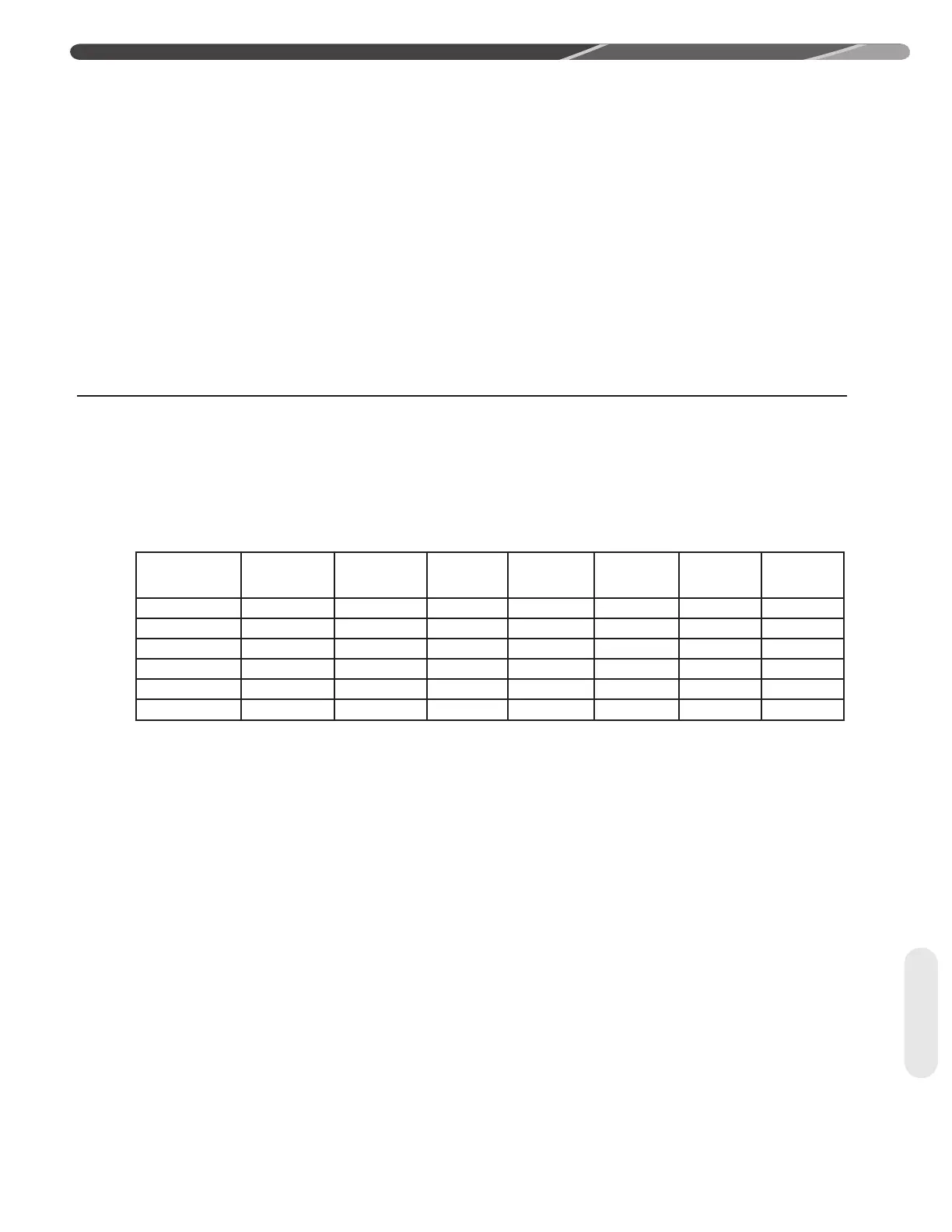
4.4.3 Line Set Length and Fitting Losses
Line Size
in [mm]
90° Short
Radius
Elbow
90° Long
Radius
Elbow
45°
Elbow
Solenoid
Valve
Check
Valve
Sight
Glass
Filter
Drier
3/8 [9.53] 1.3 [0.40] 0.8 [0.24] 0.3 [0.09] 6 [1.83] 4 [1.22] 0.4 [0.12] 6 [1.83]
1/2 [12.71] 1.4 [0.43] 0.9 [0.27] 0.4 [0.12] 9 [2.74] 5 [1.52] 0.6 [0.18] 6 [1.83]
5/8 [15.88] 1.5 [0.46] 1 [0.30] 0.5 [0.15] 12 [3.66] 6 [1.83] 0.8 [0.24] 6 [1.83]
3/4 [19.05] 1.9 [0.58] 1.3 [0.40] 0.6 [0.18] 14 [4.27] 7 [2.13] 0.9 [0.27] 6 [1.83]
7/8 [22.23] 2.3 [0.70] 1.5 [0.46] 0.7 [0.21] 15 [4.57] 8 [2.44] 1 [0.30] 6 [1.83]
1-1/8 [28.58] 2.7 [0.82] 1.8 [0.55] 0.9 [0.27] 22 [6.71] 12 [3.66] 1.5 [0.46] 6 [1.83]