
D
David Joyce MDAug 15, 2025
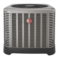
What happens if my Ruud RD17AZ Heat Pump has high refrigerant pressure?
- MMichael ReyesAug 15, 2025
In case of high refrigerant pressure (A958_O) in your Ruud Heat Pump, the system will activate a 4-hour lockout.
What happens if my Ruud RD17AZ Heat Pump has high refrigerant pressure?
In case of high refrigerant pressure (A958_O) in your Ruud Heat Pump, the system will activate a 4-hour lockout.
What happens if my Ruud RD17AZ has an AC input overvoltage inverter fault?
If your Ruud Heat Pump experiences an AC input overvoltage inverter fault (A948_O), it will shut down and restart once the fault is cleared.
What happens if the pressure relief valve is stuck open on my Ruud Heat Pump?
If the pressure relief valve is stuck open (T012_O) on your Ruud Heat Pump, the system is disabled while active.
What happens if the pressure relief valve is stuck closed on my Ruud RD17AZ?
If the pressure relief valve is stuck closed (T011_O) on your Ruud Heat Pump, the system is disabled while active.
What happens if my Ruud Heat Pump has an inverter communication fault?
If your Ruud Heat Pump experiences an inverter communication fault (A915_O), the system will shut down and restart upon clearing the fault.
What happens if there is a Fan 1 fault on my Ruud RD17AZ Heat Pump inverter?
If there is a Fan 1 fault (A815_O) on your Ruud Heat Pump inverter, the system will experience a 3-strikes permanent lockout.
What does 'Locked Out - See History Faults' mean on my Ruud RD17AZ Heat Pump?
If your Ruud Heat Pump displays 'Locked Out - See History Faults' (A928_O), it indicates a permanent lockout.
What happens when there is a suction pressure sensor failure in my Ruud Heat Pump?
If your Ruud Heat Pump experiences a suction pressure sensor failure (A956_O), the algorithms will default.
What happens when there is a suction temperature thermistor failure in my Ruud RD17AZ?
If your Ruud Heat Pump experiences a suction temperature thermistor failure (A954_O), the algorithms will default.
What happens when there is a coil temperature thermistor failure in my Ruud RD17AZ Heat Pump?
If your Ruud Heat Pump experiences a coil temperature thermistor failure (A953_O), the algorithms will default.
Crucial warnings regarding electrical shock, property damage, injury, or death.
Important notes on refrigerant handling, system matching, and potential hazards.
Emphasizes critical factors for safe, reliable, and satisfactory operation.
Guidance on calculating heating/cooling loads for proper system specification.
Criticality of matching components for optimal performance and warranty.
Breakdown of model number coding and available unit configurations.
Key electrical ratings, dimensions, and clearances for the unit.
Essential tools, R-410A specifications, and quick reference guide for installation.
Guidelines for selecting an optimal site for unit placement to ensure performance.
Specifies minimum space requirements around the unit for airflow and service.
Addresses potential problems from unit placement, like water runoff or airflow obstruction.
Warnings and advice on protecting the unit from corrosive elements.
Methods for securely mounting the unit on various surfaces.
Procedures for elevating the unit to prevent snow damage or ensure stability.
Guidelines for choosing and sizing refrigerant lines for system efficiency.
Procedures for adapting or replacing existing line sets for new R-410A units.
Factors affecting line set performance like oil return, pressure drop, and migration.
How tubing length and fittings impact pressure and capacity.
Guidance on selecting the correct liquid line size to prevent flashing.
Importance of vapor line sizing for proper oil return and system performance.
Table providing specific line size recommendations based on system capacity and length.
Proper techniques for routing, supporting, and connecting refrigerant tubing.
Key practices for ensuring tubing integrity and performance during installation.
How the vertical and horizontal placement affects line set requirements.
Specific requirements for installations where units are on the same level.
Installation guidelines for systems with the outdoor unit positioned lower than the indoor unit.
Installation guidelines for systems with the outdoor unit positioned higher than the indoor unit.
Procedures for making proper brazed connections for refrigerant lines.
Steps for pressurizing the system with nitrogen to check for leaks.
Critical process for removing air and moisture from the system using a vacuum.
Final leak detection after evacuation and charging.
Instructions for connecting low-voltage control wires to the system.
Wiring diagrams for using a standard 24VAC thermostat.
Overview of the communicating system and its benefits.
Guidelines for mounting and installing the EcoNet™ Control Center.
Specific wiring requirements for EcoNet™ system components.
Wiring instructions for limited thermostat wire configurations.
Procedures for connecting the unit to the main power supply.
Essential steps for properly grounding the unit for safety.
General steps for bringing the system online and verifying operation.
Steps to power the system and confirm communication between components.
Configuration steps for the EcoNet™ Control Center.
Steps to put the system into charging mode for verification.
Detailed steps to activate charging mode via the EcoNet™ Control Center.
Instructions for initiating charge mode using a standard thermostat.
Ensures correct airflow for optimal system performance and comfort.
Procedures for checking and adjusting refrigerant charge for optimal operation.
Proper connection and use of measurement tools for charging.
Method for calculating and adding refrigerant based on system weight.
Optional method for checking charge using pressure readings.
Final charge adjustment using liquid subcooling for precise system tuning.
Final steps including disconnecting hoses and restoring power.
Describes the different operational modes of the unit.
Explains the automatic humidity control feature.
How the unit operates in low outdoor temperatures for cooling.
How auxiliary electric heat integrates with the heat pump.
System's process for preventing and clearing ice buildup on the outdoor coil.
Details on the main control board's features, connections, and factory superheat setting.
How the inverter manages compressor speed for efficient operation.
Monitors and protects against low refrigerant pressure conditions.
Describes the system's response to pressure-related faults.
How the system operates when a sensor fails, ensuring basic functionality.
Protects against excessive current and phase imbalances.
Shuts down the system if voltage levels are outside the acceptable range.
Protects the inverter from overheating by reducing compressor speed.
Procedure for clearing system lock-outs after protection features are engaged.
List of EcoNet fault codes and their corresponding response actions.
Detailed charts for diagnosing system problems based on symptoms and causes.
Procedures for testing and validating transducer and sensor performance.
A quick reference table linking system symptoms to possible causes and remedies.
Practical advice for diagnosing common system problems in cooling and heating modes.
Steps for cleaning the outdoor coil to maintain airflow and efficiency.
Guidelines for cleaning and protecting the unit's exterior cabinet.
Information on motor lubrication, noting it's pre-lubricated.
Electrical schematic specific to heat pump configurations.
Electrical schematic for air conditioner configurations.
Detailed steps for conducting performance audit tests on the unit.
| SEER | Up to 17 |
|---|---|
| HSPF | Up to 9.5 |
| Refrigerant | R-410A |
| Stages | Single Stage |
| Cooling Capacity (BTU/h) | 18, 000-60, 000 |
| Heating Capacity (BTU/h) | 18, 000-60, 000 |
| Tonnage | 1.5-5 Tons |
| Warranty | 10-Year Limited Warranty |