23
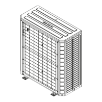
• After adequate evacuation, open both service valves
by removing both brass service valve caps with
an adjustable wrench. Insert a 3/16" [5 mm] or
5/16" [8 mm] hex wrench into the stem and turn
counterclockwise until the wrench stops.
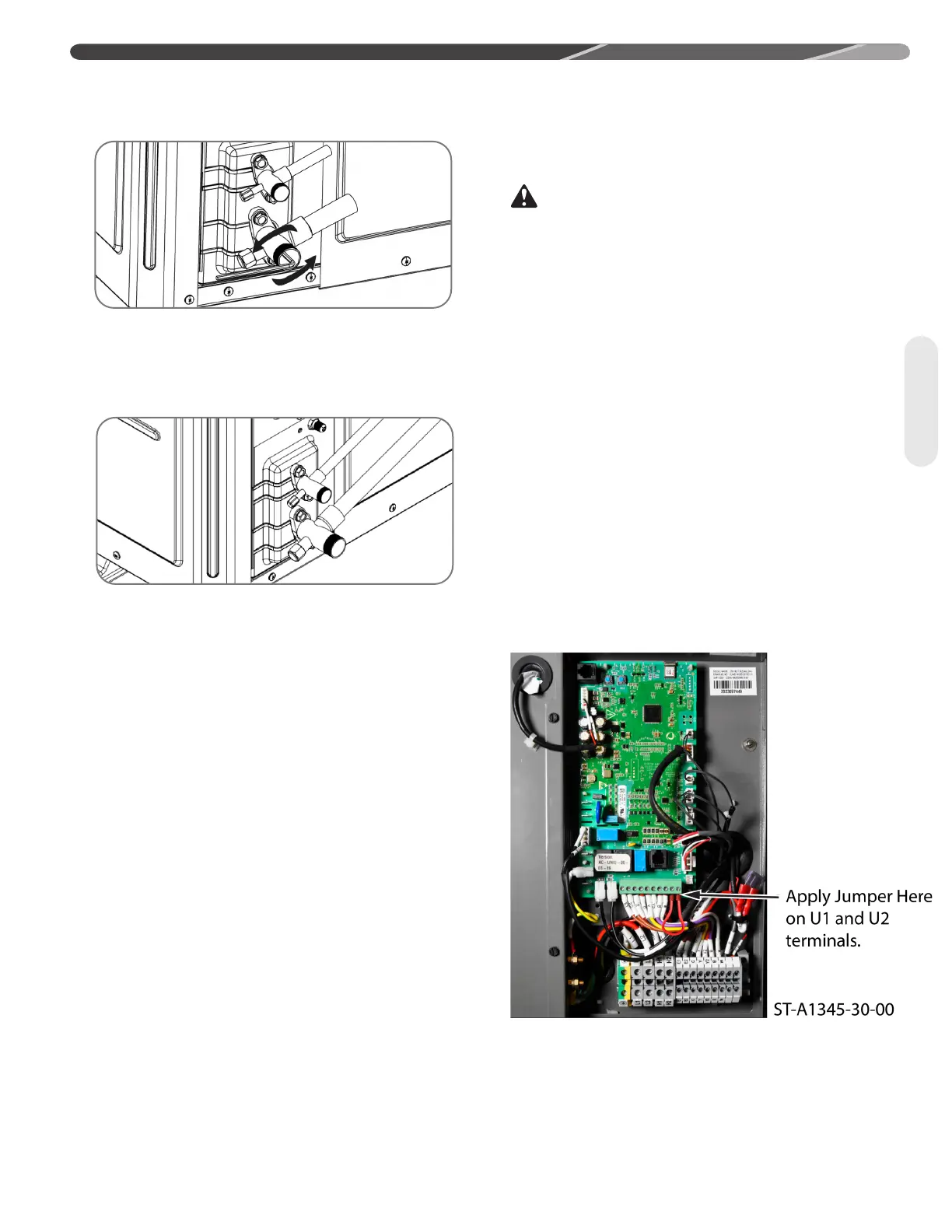
• If not already connected from evacuation process,
gauges must be connected at this point to check and
adjust charge.
IMPORTANT: Compressors should never
be used to evacuate the air conditioning system because
internal electrical arcing in near vacuum conditions
may result in a damaged or failed compressor. Never
run a compressor while the system is in a vacuum or
compressor failure will occur.
4.8 Final Leak Testing
After the unit has been properly evacuated and service
valves opened, a halogen leak detector should be
used to detect leaks in the system. All joints and piping
within the outdoor unit, indoor coil, and interconnecting
tubing should be checked for leaks. If a leak is
detected, the refrigerant should be recovered before
repairing the leak. The Clean Air Act prohibits releasing
refrigerant into the atmosphere.
4.9 Control Wiring
WARNING: Turn off electric power at the
fuse box or service panel before making any electrical
connections. Also, the ground connection must be
completed before making line voltage connections.
Failure to do so can result in electrical shock, severe
personal injury, or death.
4.9.1 For Installations with existing
single stage indoor coil and furnace
or air handler
For installations that use an existing indoor coil and
furnace or an existing indoor air handler, the indoor
should be modied to allow use of a 2 stage thermostat.
See diagrams below for wiring instructions. A relay will
need to be provided for installation that is rated for the
voltage and current that will be passing through the
relay. Note that the low stage airow should be 75%
of high stage.
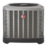
For matchups with a non-matching indoor air mover
and coil, the utility terminals on the UODC board can
be shorted to invoke an alternate mode of operation
that allows the system to adapt to reasonably mis-
matched coils. The jumper is applied to terminals U1
and U2 on the UODC board.
Wiring
4.0 INSTALLATION