25
Wiring
4.0 INSTALLATION
4.9.2 Conventional 24VAC Thermostat
Control Wiring Connections
The RD17AZ series of heat pumps allow the installer to
use conventional 24 VAC control wiring and a conventional
thermostat for limited unit operation. The system will
operate as a single stage system at nominal capacity.
IMPORTANT: The preferred method of unit installation
and operation is by the EcoNet™ Communicating
System which allows access to the fault history of the
system. This diagnostic information is not available at the
thermostat when the RD17AZ unit is using a conventional
thermostat.
Thermostat control wiring requires a minimum of four (4)
wires for proper unit operation:
C – 24 VAC common
Y1 – Nominal capacity operation
B – Heat pump operation
W – Supplemental Heat During Defrost Cycle
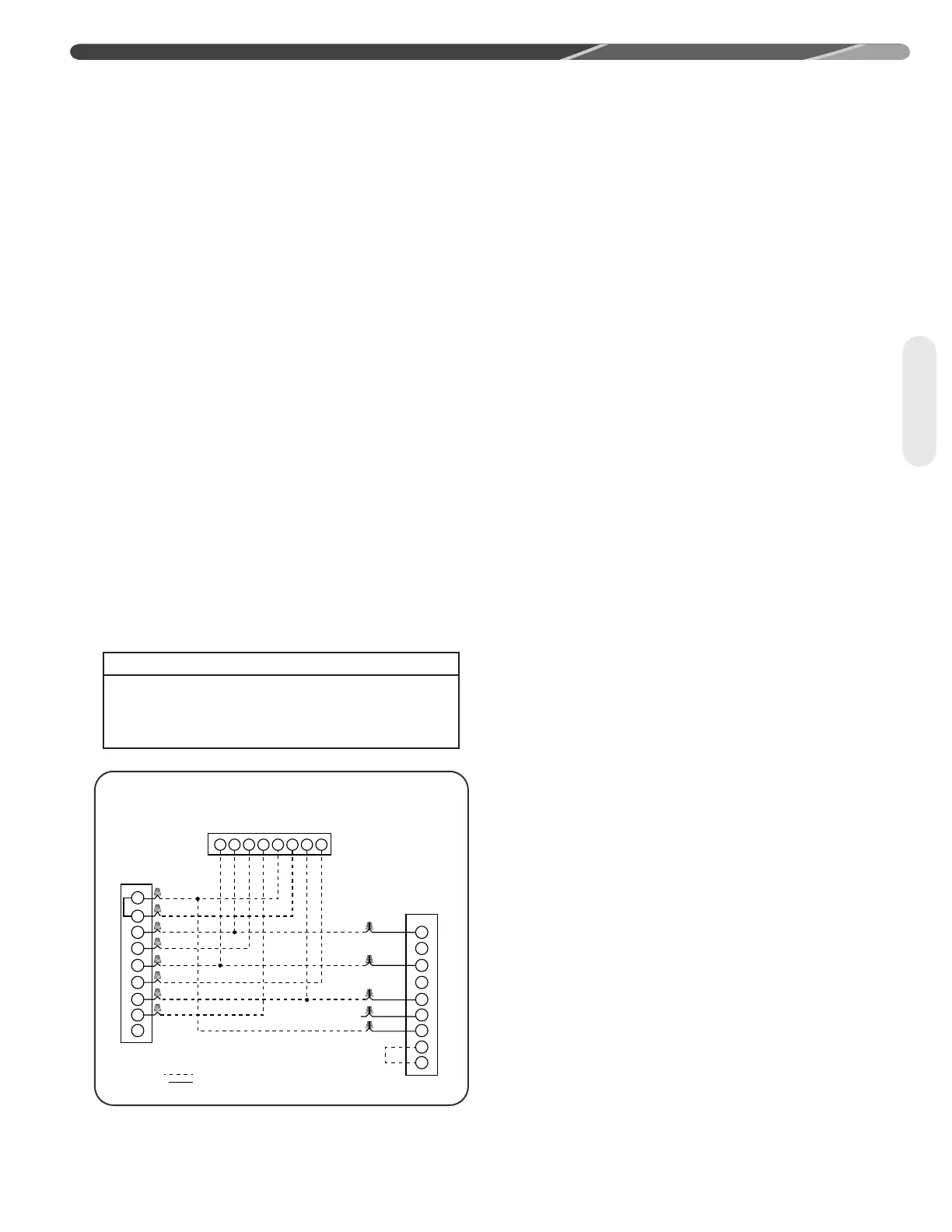
The following figures show the typical control
wiring diagrams with RD17AZ heat pumps using a
conventional 24VAC thermostat. Adjust indoor airflow
using the Bluetooth Contractor's App (Dipswitches are
not available).
4.9.3 EcoNet
™
Communications
The EcoNet
TM
enabled RD17AZ Series heat pumps are
specifically designed to be matched with and EcoNet
TM
enabled air-handler or gas furnace and the EcoNet
TM
Control Center. While they are also designed to be
controlled by a conventional 24VAC 2-stage thermostat,
many features and benefits are lost.
4.9.4 EcoNet
™
Control Center
Installation
The EcoNet
TM
Control Center should be mounted 4 to 5
feet [1.2 to 1.5 m] above the floor on an inside wall of
the living room or a hallway that has good air circulation
from the other rooms being controlled by the Control
Center. It is essential that there be free air circulation at
the location of the same average temperature as other
rooms being controlled. Movement of air should not
be obstructed by furniture, doors, draperies, etc. The
Control Center should not be mounted where it will be
affected by drafts, hot or cold water pipes or air ducts in
walls, radiant heat from fireplace, lamps, the sun, T.V. or
an outside wall. See instructions packaged with Control
Center for detailed mounting and installation instructions.
WIRE COLOR CODE
BK – BLACK GY – GRAY W – WHITE
BR – BROWN O – ORANGE Y – YELLOW
BL – BLUE PR – PURPLE
G – GREEN R – RED
B
W1
W2
Y1
Y2
B
R
C
G
Y1
Y2
B
R
C
L
D
U1
U2
ODD
Y1 Y2 G
EW1
W2 C R
Y
2-Stage
Heat Pump
Outdoor
Unit
BL
BR
W/R
PR
Air
Handler
*
WIRING INFORMATION
Low Voltage
-Field Installed
-Factory Installed
Typical Two-Stage Thermostat
2-STAGE HEAT PUMP WITH ELECTRICAL HEAT USING A TYPICAL
2-STAGE THERMOSTAT WITH JUMPER APPLIED TO U1 AND U2 TERMINALS.
ST-A1345-20-00