26
Wiring
4.0 INSTALLATION
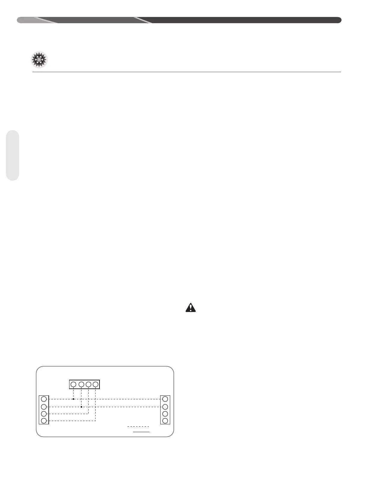
EcoNet™
Control Center
Indoor
Unit
Outdoor
Unit
Field-Installed
Factory Standard
E1 E2 R C
E1
E2
R
C
E1
E2
R
C
ST-A1345-19-00
4.9 Control Wiring (cont.)
4.9.5 EcoNet
™
Communication
Wiring Connections
The four 18 AWG low-voltage control wires must be
installed from the EcoNet™ Control Center to the
indoor unit and 2 wires from the indoor unit to the
outdoor unit. The wire length between the Control
Center and indoor unit should not be greater than
100 feet [30.5 m].
The wire length between the indoor unit and outdoor
unit should not be greater than 125 feet [38.1 m].
Running low-voltage wires in conduit with line voltage
power wires is not recommended. Low-voltage wiring
must be connected to the low voltage terminal block
on the Universal Outdoor Control. The terminal block
can be unplugged from the control board to facilitate
wiring.
An EcoNet™ communicating heat pump system
consists of these matched components:
• EcoNet™ communicating outdoor unit.
• EcoNet™ communicating air handler or
EcoNet™ communicating furnace.
• EcoNet™ Control Center.
IMPORTANT: The EcoNet™ control
system requires continuous 18 AWG thermostat
wire. Do not use phone cord to connect indoor
and outdoor units. This will damage the controls.
The EcoNet™ control system requires four (4) control
wires for unit operation between the indoor unit and
Control Center. 2 wires are required from the indoor
unit to the outdoor unit (E1, E2):
• Data wire E1 Communications
• Data wire E2 Communications
The EcoNet™ enabled air handler or furnace is
equipped with a 24-volt, 40 or 50 VA transformer
for proper system operation. See the wiring diagram
below for low voltage wiring connections.
These wires need to be connected to each device
(Control Center, indoor air handler or furnace, and
outdoor unit).
Once all devices are connected, apply the line
voltage to the indoor and outdoor units.
When all devices are powered, the EcoNet™ Control
Center should detect the indoor and outdoor units
within 45 seconds.
Once the system is powered and all components are
communicating with each other, the airflow settings
will be automatically configured in the air-handler or
furnace.
All adjustments for indoor airflow are made at the
EcoNet™ Control Center from this point. Items
that can be changed are airflow trim adjustment,
on-demand dehumidification, cooling and heating
airflow and electric heat airflow. The Control Center
also has a wide range of fault and history information.
To access any of the control center menus press the
settings, status, or service icons at the bottom of
the touch screen. Refer to the air handler or furnace
installation manual and the EcoNet™ Control Center
installation manual for further details on setting up
the system and available adjustment options.
4.9.6 For Installations With Only
2 Thermostat Wires Between The
Indoor And Outdoor Units.
The RD17AZ outdoor unit is factory equipped with
a 24VAC transformer in the outdoor unit for use
with Econet Controls. In these installations, only the
communication wires, E1 and E2 are required to be
run from the indoor unit to the outdoor unit.
WARNING: Never route low voltage
(eg 24VAC thermostat) wiring in the same conduit or
whip as line voltage (eg 120VAC, 240VAC and etc). It
is important that proper electrical power is available at
the heat pump power terminal block. The acceptable
operating voltage range is shown below.
 Loading...