14
4.0 INSTALLATION
4.4.5 Vapor Line Selection
The purpose of the vapor line is to return superheat-
ed vapor to the condensing unit from the indoor coil
in the cooling mode. While in the heating mode, the
vapor line transports discharge vapor to the indoor
coil from the outdoor unit. Proper vapor line sizing
is important because it plays an important role in
returning oil to the compressor to prevent poten-
tial damage to the compressor. Also, an improperly
sized vapor line can dramatically reduce capacity
and performance of the system. The procedure for
selecting the proper vapor line is as follows:
• Determine the total linear length of vapor line re-
quired.
• Add all of the equivalent lengths associated with
any ttings or accessories using Table 1.
• Add the linear length and total tting equivalent
length. This will equal your total equivalent line
length.
• Reference Table 2 to verify that the calculated
equivalent length falls within the compatibility re-
gion of the chart.
• Verify capacity loss is acceptable for the applica-
tion.
Tubing
4.4.4 Liquid Line Selection
The purpose of the liquid line is to transport warm
sub-cooled liquid refrigerant between the outdoor
unit to the indoor unit in the cooling mode. In the
heating mode, the liquid line returns sub-cooled liquid
from the indoor unit to the outdoor unit. It is important
not to allow the refrigerant to ash into superheated
vapor prior to entering the expansion device of the
indoor coil or outdoor unit. Flashing of refrigerant can
occur for the following reasons:
• Low refrigerant charge
• Improperly selected liquid line size
• Absorption of heat prior to expansion device
• Excessive vertical separation between the outdoor
unit and indoor coil
• Restricted liquid linear lter drier
• Kinked liquid line
The total pressure drop allowed for the liquid line is
50 PSI [345 kPa]. The procedure for selecting the
proper liquid line is as follows:
• Measure the total amount of vertical separation be-
tween the outdoor unit and indoor coil.
• Measure the total indoor length of liquid line re-
quired.
• Add all of the equivalent lengths associated with
any ttings or accessories using Table 1.
• Add the linear length to the total tting equivalent
length. This will equal your total equivalent line
length.
• Reference Table 2 to verify the calculated equiva-
lent length is acceptable with the required vertical
separation and diameter of liquid line.
Example: A 3-ton heat pump unit is installed 25’ be-
low the indoor unit, requires a 75’ of 1/2” diameter
liquid line, 3/4" vapor line, 4 90° LR elbows and a
lter drier.
• Fitting Equivalent Length (ft.) = 4 × .9' + 6' = 9.6’
• Total Equivalent Length (ft.) = 75’ + 9.6' = 84.6’
This application is acceptable because the 25’ verti-
cal rise is less than the maximum rise of 50’ for this
application.
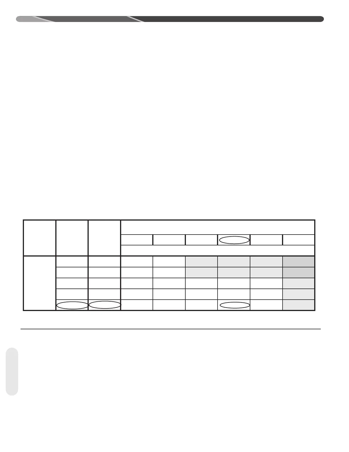
Example Table (Excerpt from Table 2A)
Unit Size
Allowable
Liquid Line
Size
Allowable
Vapour
Line
Size
Outdoor Unit ABOVE or BELOW Indoor Unit
Equivalent Length (Feet)
< 25 26-50 51-75 76-100 101-125 126-150
Maximum Vertical Separation / Capacity Multiplier
3 Ton
5/16" 5/8" 25 / 0.99 50 / 0.97 50 / 0.95 50 / 0.93 36 / 0.91 NR
3/8" 5/8" 25 / 0.99 50 / 0.97 50 / 0.95 50 / 0.93 50 / 0.91 NR
5/16" 3/4" 25 / 1.00 50 / 0.99 50 / 0.99 50 / 0.98 36 / 0.97 20 / 0.96
3/8" 3/4" 25 / 1.00 50 / 0.99 50 / 0.99 50 / 0.98 50 / 0.97 50 / 0.96
1/2" 3/4" 25 / 1.00 50 / 0.99 50 / 0.99 50 / 0.98 50 / 0.97 50 / 0.96
 Loading...