Revision 4 - December 17,1998 Ryan TCAD 9900 Series Page 6-3
If any lines are shorted or open, several (but not all) altitudes on the TCAD will be in
error. By using the static tester and raising the altitude of the encoder, a malfunction can
be determined by watching the TCAD Display (set to 29.92) as the altitude from the
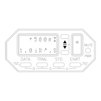
encoder goes up. If stars appear in place of an altitude indication, or the altitude on the
TCAD differs from the altitude on the static system tester, note which altitudes are wrong
and what the indications are. Then, by referring to the altitude squawk table found in
most transponder manuals you can usually determine which combination of bits is causing
the errors. Then it is possible to identify which wires are shorted or open.
Stars (∗∗∗∗∗∗) on the altitude display indicate the TCAD is not receiving valid altitude
data.
The common line from the TCAD to the encoder should never be diode isolated. If it is,
improper and unpredictable altitude errors will result. The encoder lines should be
shielded, with the shield grounded at one end.
6.2.6 TRANSPONDER SUPPRESSION
TCAD sends and receives suppression signals. Transponder and DME suppression are
required. Verification that suppression is operating is essential during checkout of the
TCAD.
TCAD is compatible with both mutual and unidirectional suppression systems.
Figure 2-2 lists the availability of suppression for popular transponders.
TCAD suppression can be connected directly to any ARINC-standard mutual suppression
bus. Since not all transponder suppression configurations conform to ARINC standards,
components must be added to bring some suppression circuits closer to conformity. See
Figure 2-16.
If a diode is called out in the Installation Manual, it should be installed at the transponder
to avoid any capacitive charge build-up. The following items may cause an unsatisfactory
suppression signal:
1) Suppression not connected.
REMEDY: Connect it.
2) The diode used to block TCAD suppression from
sinking into the DME is installed backwards.
REMEDY: Install the diode correctly.
Best performance of TCAD is obtained when the DME and transponder are operating
properly. Many aircraft have interference between the DME and transponder and DME
interference cannot always be detected. If the DME causes the transponder to transmit
often, there is much less time available for TCAD to acquire data.
To assure no interference from the DME, always connect DME suppression.