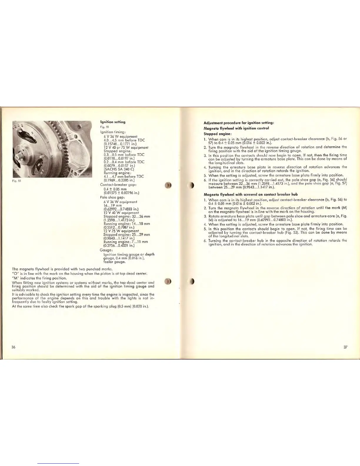
Ignition $etting
Fig.
55
Ignition
ti
ming:
6 V 36 W
equipment
4.0
...
4.5
mm
before
TDC
(0.15748 ... 0.
1771
in.)
12
V 40
or
75 W
equipmen
t
Stopped
engine:
0.3 ... 0.5 mm
before
TDC
(0.0118 ... 0.0197 in.)
0.2
...
0.4
mm
before
TDC
(0.0079 ... 0.0157 in.)
(SACHS SA 340
C)
Running
engine:
4.1 .. .4.7 mm
before
TOC
(0.1969 ... 0.2205 in.)
Contod-breaker
gop:
0.4 ± 0.05
mm
(0.01575 ± 0.00196 in.)
Pole
shoe
gop:
6 V 36 W
equipment
16
..
,19
mm
(0
.62992 ... 0.74803
in.)
12
V
40
W
equipment
Stoppe
d
engine:
32 ... 36
mm
(1.2598
...
1.4173 in.)
Running
engine:
14
...
18
mm
(0.5512 ... 0.7087 in.)
12
V
75
W
equipment
Slopped
engine:
25
...
29
mm
(0
.9843 .. . 1.1417 in.)
Running
engine:
7 ..
11
mm
(0.2756 ...
0.4331
in.)
Gouge:
Ignition timing
gouge
or
depth
gouge,
0.4 mm (0.016 in.),
feeler
gauge.
The
magne
to flywheel
is
provi
ded
with two punched marks.
"
0"
is
in line
wi
th I
he
mark on Ihe housing when the piston
is
a t
top
dead
center.
"
M"
indicates the
fi
ring
po
sition.
When
fitting new ignition systems
or
systems without marks,
the
top
dead
center
and
firing
pos
iti
on
should be determined with the
aid
of the ignition timing
gauge
and
su
i
tably
marked.
It
is
adv
i
sable
to
check the ignition setting every lime
the
engine
is
insp
ected,
since the
perform
anc
e of Ihe
enQ
ine
depends
on this
and
trouble
with
the
lights
is
not in-
frequently
du
e to fa
ul
ty Ignition setting.
At the
sam
e t
im
e a lso c
he
ck
the
spa
rk
gop
of the sparking plug
(0.5
mm)
(0.020
in.).
36
Adiustment
procedure
for ignition setting:
Magneto
fly
wheel with ignition control
Slopp
ed e
ngine:
1.
When
cam
is
in
its
highest position,
adjust
contact-breoker
cl
e
arance
(b, Fig. 56
or
57)
to
0.4 ± 0.05
mm
(0
.016 ± 0.002 in.).
2. Turn
the
magneto
flywheel
in
the rever
se
direction
of
rotat
i
on
and
determine
the
firing positi
on
w
it
h the
aid
of
the
ignition timing
gouge.
3.
In
this positi
on
the contacts should now begin to
open.
If
nol, then the firing time
can
be
ad
jus
ted by turning the
armature
bose
plate. This
can
be
done
by
means
of
t
he
longitudinal slots.
4. Turning the a rma ture
bose
plate
in
reverse direction of
rotation
advances
the
ignition,
and
in
the
di
rection of rotation
retards
the ignition.
5.
When
Ihe setting
is
adiusted,
screw Ihe
armature
base
plate
firmly inlo position.
6.
If
the
ignition setting
is
correctly
car
ried out, the
pole
shoe
gap
(0,
Fig
.
56)
should
measure
be
t
ween
32
...
36
mm
(1
.2598
...
1.4173 in.),
and
the
pale
shoe
gap
(a,
Fig.
57)
be
t
ween
25
...
'E
mm
(0
.9843 ... 1.1417 in.).
Magneto
flywheel wilh scre
we
d
on
conlact
breaker
hub
1.
When
com
is
in
its
highest position,
adjust
contac
t-
breaker
clearance
(b,
Fig.
56)
to
0.4 ± 0.05
mm
(0.016 ± 0.002
in
.).
2. Turn
the
magneto
fl
ywheel
in
the
reverse direction
of
rotation
until the
mar
k
(M)
on
the
magneto
flywheel
is
in
line with
the
mark
on
the
housing.
3.
Rotate
ormature
base
plate
until
gop
be
t
ween
pole
shoe
and
a r
mature
core
(a, F
ig.
56)
is
adjusted
to
16
...
19
mm
(0.62992 ... 0.74803
in
.
).
4.
When
the
setting
is
adjusted,
screw
the
armature
bose
plate
firmly into position.
5.
In
this position
the
contac
ts should begin
to
open.
If nat, the firing time
can
be
adjus
t
ed
by turning
the
cont
act-breaker
hub
(Fig . 53).
Th
is
can
be
done
by
means
of
the longitudi
na
l slots.
6. Turning
the
contact-
breake
r
hub
in
the
oppos
i
te
direction
of
rotation
retards
th
e
ignition,
and
in
the direction
of
rota
tion
advances
the
ignition.
37