securing metal plates of the mechanical assembly rubber stops.
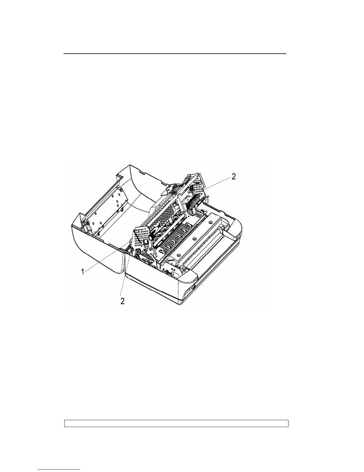
- Lift the front part of the mechanical assembly off the base of the printer,
partly rotating it until you are able to reach the connectors on the main
board.
- Unplug the printhead cable, the carriage movement motor cable and the
carriage reset photosensor cable from the main board.
- Remove the console cable connector (1) from the left rear side of the
frame.
- Remove the two rear side screws (2) so as to detach the upper part of
the mechanical assembly.
Fig. 6-4
6.3.6. PRINTHEAD DISASSEMBLY/REASSEMBLY
- Open the printer cover and lift the mechanical assembly.
- Remove the ribbon cartridge.
- Unscrew the two screws (1) that secure the printhead.
- Release the two fasteners(2) from the printhead cable support, down the
printhead cable support out and insert it into the back of the printhead.
- Partly slide off the printhead from the carriage and unplug the two