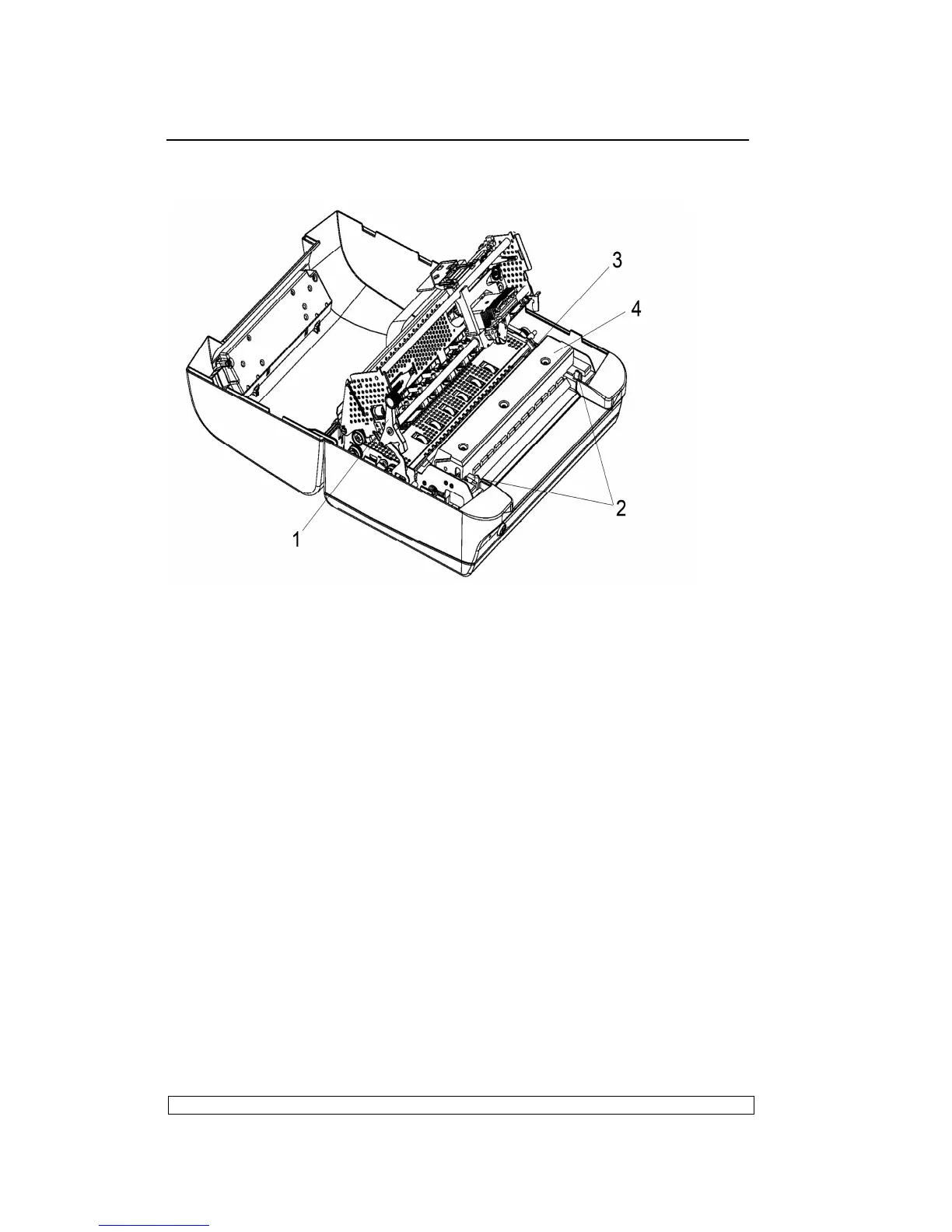
Fig. 6-3
6.3.4. MECHANICAL ASSEMBLY DISASSEMBLY/REASSEMBLY
- Remove the printer case (6.3.1)
- Loosen screws and unhooking the securing plates of the mechanical
assembly 4 rubber stops.
- Remove the console cable by unplugging it connector from the left rear
side of the frame.
- Lift the front part of the mechanical assembly, partly rotating it until you
are able to reach the connectors on the main board.
- Remove the soundproofing and unplug all the cables connecting the
mechanical assembly to the main board, with the exception of the main
board-to-power supply unit connection cable.
- Lift the entire mechanical assembly from the base of the printer.
6.3.5. UPPER PART OF THE MECHANICAL ASSEMBLY
DISASSEMBLY/REASSEMBLY
- Remove the printer case (6.3.1)
- Loosen 2 screws in the left side and right side and unhooking the