Note:
After reassembly, correctly reposition ground spring and then adjust
the carriage feed belt.
Fig. 6-7
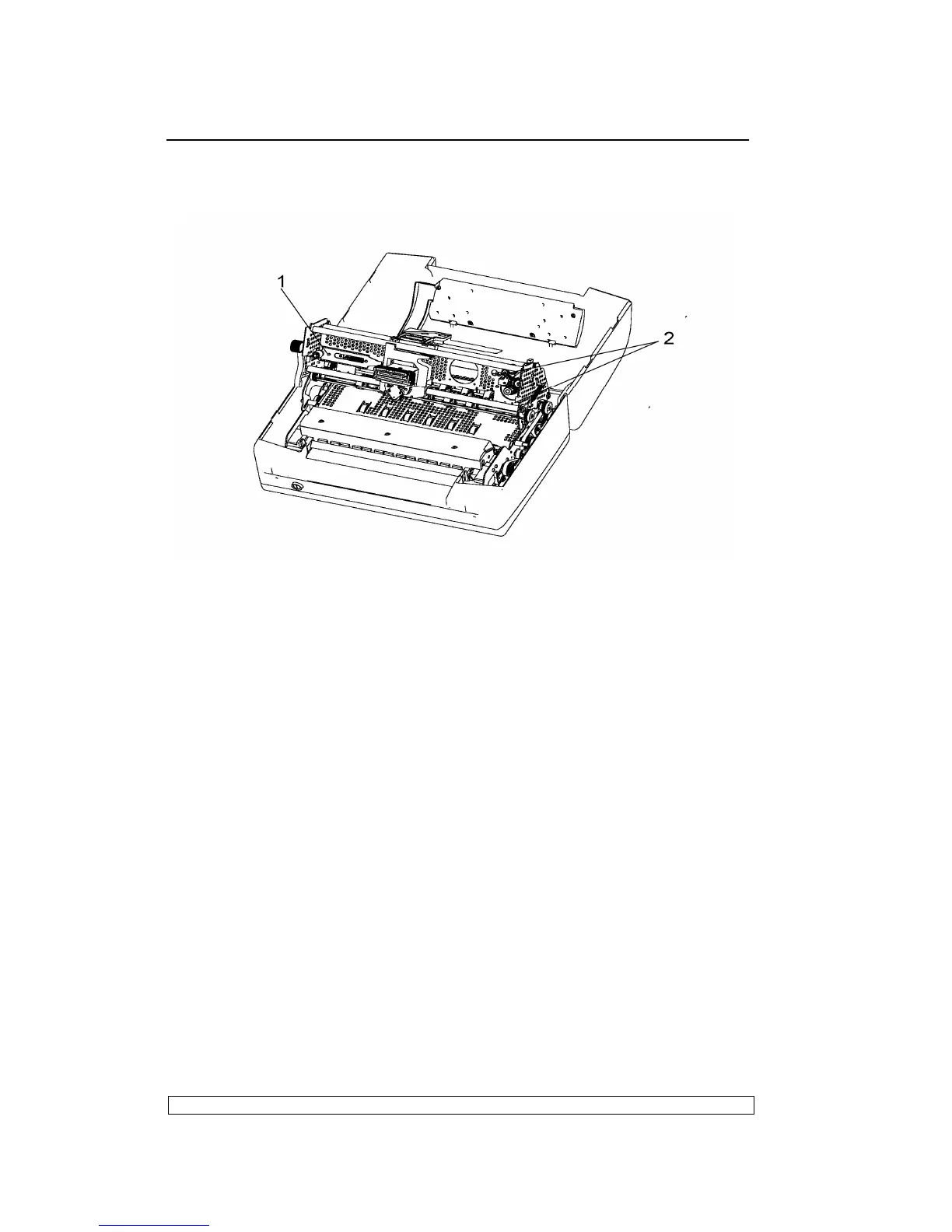
6.3.11. SERVICES MOTOR DISASSEMBLY/REASSEMBLY
- Remove the printer case (6.3.1)
- The services motor is situated the left side of the mechanical assembly.
- Lift the front part of the mechanical assembly, partly rotating it until you
are able to reach the connectors on the main board.
- Unplug the services motor connection cable from the main board.
- Remove the two screws (1) that secure the motor in left-hand side of the
frame and remove the services motor from the machine.
6.3.12. PRINTHEAD RESET PHOTOSENSOR
DISASSEMBLY/REASSEMBLY
- Remove the printer case (6.3.1)
- Loosen screws and unhooking the securing plates of the mechanical
assembly rubber stops.
- Lift the front part of the mechanical assembly, partly rotating it until you
are able to reach the connectors on the main board.
- Unplug the printhead reset photosensor cable from the main board.
- Remove the photosensor by unscrewing the screw (1).