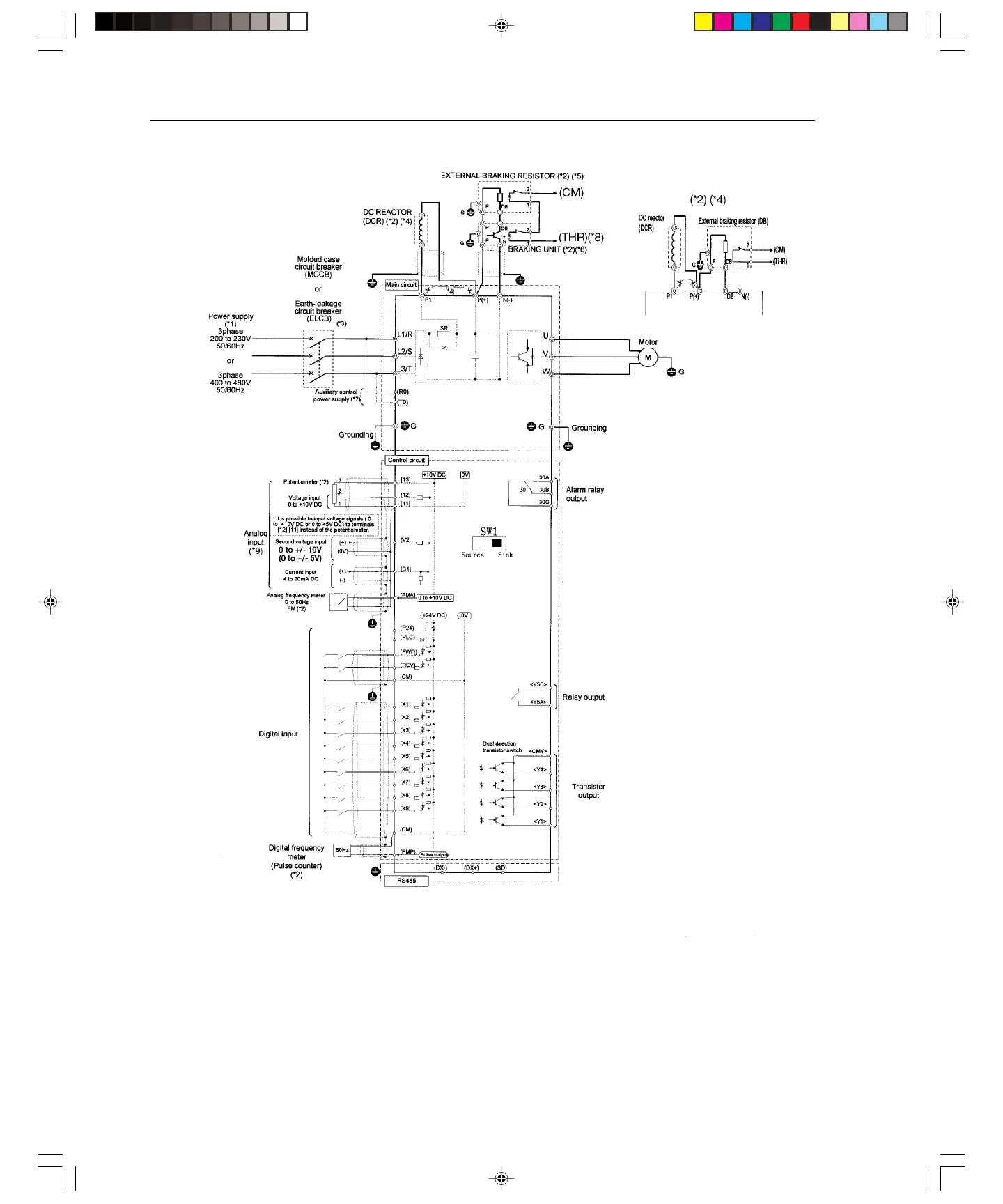
11
Note: The control circuit common terminals [11], (CM) and <CMY> are isolated
(*1) Use a drive with rated voltage matching the power supply voltage.
(*2) Use as required.
(*3) Use this peripheral device when necessary.
(*4) Remove the jumper wire between P1 and P(+) before connecting a DC REACTOR.
(*5) Be sure to use the braking unit (option) when connecting the external braking resistor (option)
(*6) Connect the braking unit to P(+) ans N(-). The auxiliary terminals [1] and [2] have polarity.
Connect them as shown in the figure above.
(*7) The drive can be operated without connecting the auxiliary control power supply.
(*8) Terminal (X1) to (X9) can be set to 9 (THR) - Braking unit thermal trip input.
(*9) If using V2 or C1, as a reference signal, they must be used exclusively.
(*10) It is possible to input voltage signals (0 to +10 VDC or 0 to +5 VDC) to terminals [12] [11] instead of the potentiometer
.
Basic Connection Diagram (Sink Logic)
20 Hp and above Up to 15 Hp
Artisan Technology Group - Quality Instrumentation ... Guaranteed | (888) 88-SOURCE | www.artisantg.com