18
Connecting the Control Terminals
The table below lists the functions of the control circuit terminals. A control circuit terminal should be connected according
to its function setting.
Terminal
Classification Symbol Terminal Name Function
Analog input 13 Potentiometer power supply Used for +10V DC power supply for frequency setting POT
(resistance of 1 to 5k Ohms)
12 Voltage input 1. Frequency is set according to the analog input voltage
supplied from an external circuit.
- 0 to +10V DC / 0 to 100%
- Reversible operation using positive and negative signals:
0 to +/- 10V DC / 0 to 100%
- Reverse operation: +10 to 0V DC / 0 to 100%
2. Input feedback signal for PID control is input.
3. The analog input value from the external circuit is used
for torque control
* Input resistance: 22 k Ohms
V2 Voltage input ¨ Frequency is set according to the analog input voltage
supplied from an external circuit.
- 0 to +10V DC/0 to 100%
- Reverse operation: +10 to 0V DC/0 to 100%
* Use only one terminal - V2 or C1 Exclusively
* Input resistance: 22 k Ohms
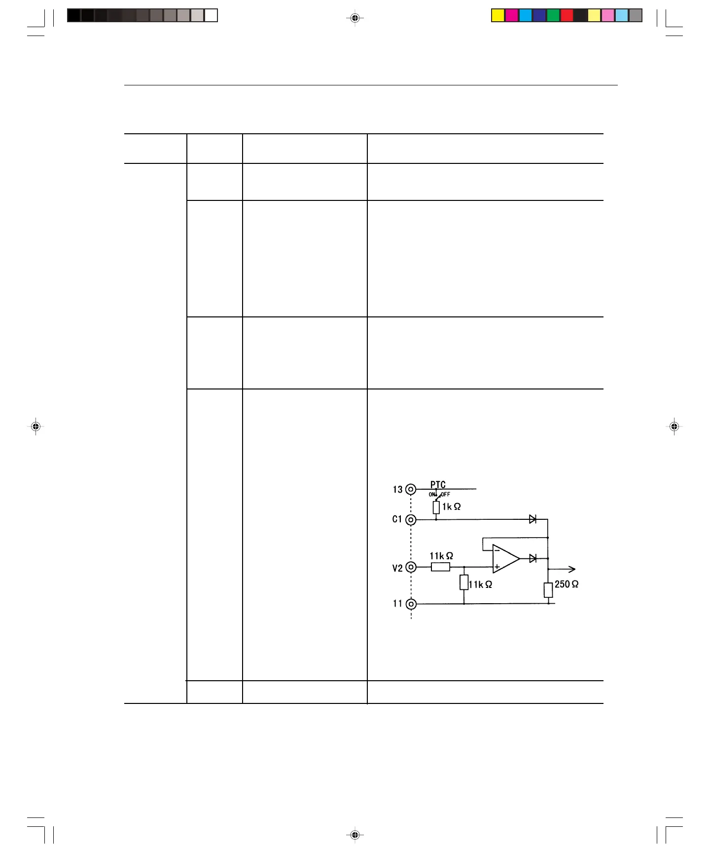
C1 Current input 1. Frequency is set according to the analog input current supplied
from an external circuit.
- 4 to 20mA DC / 0 to 100%
- Reverse operation: 20 to 4mA DC / 0 to 100%
2. The feedback signal for PID control is input.
3. PTC thermistor input
* Use only one terminal - V2 or C1 Exclusively
* Input resistance: 250 Ohms
* PTC switch is off when PTC function is not used
11 Analog input common Common terminal for analog input signals
Artisan Technology Group - Quality Instrumentation ... Guaranteed | (888) 88-SOURCE | www.artisantg.com