E
Emily RogersAug 15, 2025
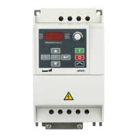
How to clear a fault on Saftronics HPVFE?
- Mmatthew43Aug 15, 2025
To resolve a faulted Saftronics DC Drive: * Clear the fault. You can do this by pressing the Stop button, cycling the power, and setting parameter A450 [Fault Clear] to option 1, which is “Clear Faults”. * If parameter t201 - t202 [Digital Inx Select] is set to option 7 “Clear Fault”, you can also clear the fault by cycling the digital input.