Sailer Manual HPVFE
18
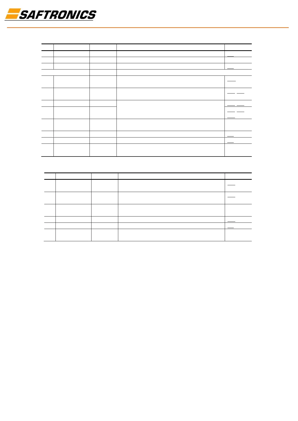
Normally open contact for output relay.
Normally closed contact for output relay.
Inputs can be wired as Sink (SNK) or Source (SRC) via DIP Switch setting.
The factory installed jumper or a normally closed input must be present
for the drive to start.
Command comes from the integral keypad by default. To disable
reverse operation, see A095 [Reverse Disable].
Command comes from the integral keypad by default. To disable
reverse operation, see A095 [Reverse Disable].
For digital inputs. Electronically isolated with digital inputs from analog
I/O.
Program with t201 [Digital In1 Sel].
Program with t202 [Digital In2 Sel].
Drive supplied power for digital inputs.Maximum output current is
100mA
I/O Wiring Examples
Drive supplied power for 0-10V external potentiometer. Maximum
output current is 15mA.
For external 0-10V input supply(input impedance = 100k ohm) or
potentiometer wiper.
For 0-10V In or 4-20mA In. Electronically isolated with analog inputs
from digital I/O.
For external 4-20mA input supply(input impedance = 250 ohm).
Program with t202 [Digital In2 Sel].
Terminal should be connected to safety ground - PE when using the
RS485 (DSI) communications port.
(3)Only one analog frequency source may be connected at a time. If more than one reference is connected at the same time, an undetermined frequency reference will result.