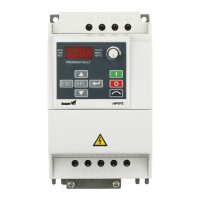
Sailer Manual HPVFE
14
Shielded
600V, 75°C or 90°C (167°F or 194°F)
RHH/RHW-2
Belden 29501-29507 or equivalent
·
Four tinned copper conductors with XLPE
insulation
·
Foil shield and tinned copper drain wire
with 85% braid coverage
·
PVC jacket
Tray rated 600V, 75°C or 90°C (167°F or
194°F) RHH/RHW-2
Shawflex 2ACD/3ACD or equivalent
·
Three tinned copper conductors with XLPE
insulation
·
5 mil single helical copper tape (25%
overlap min.) with three bare copper grounds
in contact with shield
·
PVC jacket
Class I & II;
Division I & II
Tray rated 600V, 75°C or 90°C (167°F or
194°F) RHH/RHW-2
·
Three tinned copper conductors with XLPE
insulation
·
5 mil single helical copper tape (25%
overlap min.) with three bare copper grounds
in contact with shield
·
PVC copper grounds on #10 AWG and
smaller
Reflected Wave Protection
The drive should be installed as close to the motor as possible. Installations with long motor cables may require the
addition of external devices to limit voltage reflections at the motor (reflected wave phenomena). See Table 1.E for
recommendations.
The reflected wave data applies to all frequencies 2 to 10 kHz.
For 240V ratings, reflected wave effects do not need to be considered.
Table 1.E Maximum Cable Length Recommendations
Reflected Wave
(1)
Longer cable lengths can be achieved by installing devices on the output of the drive. Consult factory for recommendations.
Output Disconnect
The drive is intended to be commanded by control input signals that will start and stop the motor. A device that
routinely disconnects then reapplies output power to the motor for the purpose of starting and stopping the motor
should not be used. If it is necessary to disconnect power to the motor with the drive outputting power, an auxiliary
contact should be used to simultaneously disable drive control run commands.

 Loading...