10
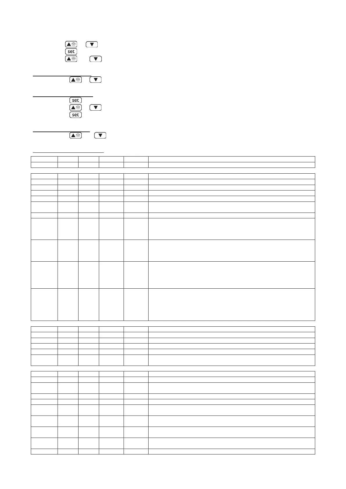
• press
or in 15 s to set “-19”
• press
or do not operate 15 s
• press
and 4 s: the display will show “SP”
To select a parameter:
• press
or
To modify a parameter:
• press
• press
or in 15 s
• press
or do not operate 15 s.
To quit the procedure:
• press
and 4 s or do not operate 60 s.
Parametri di configurazione
LABEL MIN. MAS. U.M. DEF. WORKING SETPOINTS
SP r1 r2 °C/°F (1) -20 working setpoint
LABEL MIN. MAS. U.M. DEF. MEASURE INPUTS
CA1 -25 25 °C/°F (1) -2 cabinet probe offset
CA2 -25 25 °C/°F (1) 0 evaporator probe offset
CA3 -25 25 °C/°F (1) 0 auxiliary probe offset (only if P4 = 1 or 2)
P0 0 1 - 1 kind of probe (0=PTC, 1=NTC)
P1 0 1 - 0
decimal point Celsius degree (for the quantity to show during the normal
operation) (1=
YES)
P2 0 1 - 0 unit of measure temperature (2) (0=°C, 1=°F)
P3 0 2 - 1
evaporator probe function
0=probe not enabled
1=defrost probe and thermostat probe for the evaporator fan
2=thermostat probe for the evaporator fan
P4 0 3 - 0
fourth input function0 = no probe
1 = sensor input (auxiliary probe, display probe)
2 = sensor input (auxiliary probe, condenser probe)
3 = digital input (multifunction input)
P5 0 4 - 0
quantity to show during the normal operation
0=cabinet temperature
1=working setpoint
2=evaporator temperature
3=“cabinet temperature - evaporator temperature”
P6 0 4 - 0
quantity displayed by the remote indicator
0 = cabinet temperature
1 = operational setpoint
2 = evaporator temperature
3 = "cabinet temperature - evaporator temperature"
4 = temperature detected by the auxiliary probe (only if P4 = 1 or 2)
LABEL MIN. MAS. U.M. DEF. MAIN REGULATOR
r0 0.1 15 °C/°F (1) 2 working setpoint differential
r1 -99 r2 °C/°F (1) -22 minimum working setpoint
r2 r1 99 °C/°F (1) -15 maximum working setpoint
r3 0 1 - 0 locking the working setpoint modification (1= YES)
r4 0 99 °C/°F (1) 0
temperature increase during Energy Saving function (only if P4 = 3 and i5 = 2
or 3)
LABEL MIN. MAS. U.M. DEF. COMPRESSOR PROTECTIONS (3)
C0 0 240 min 0 compressor delay since you turn on the instrument (4)
C1 0 240 min 5
minimum time between two activations in succession of the compressor; also
compressor delay sincethe end of the cabinet probe error (5) (6)
C2 0 240 min 3 minimum time the compressor remains turned off (5)
C3 0 240 s 10 minimum time the compressor remains turned on
C4 0 240 min 10
time the compressor remains turned off during the cabinet probe error; also
look at C5
C5 0 240 min 10
time the compressor remains turned on during the cabinet probe error; also
look at C4
C6 0 200 °C/°F (1) 80
condenser temperature above which the condenser overheating alarm is
activated (only if P4 = 2) (7)
C7 0 200 °C/°F (1) 90
condenser temperature above which the compressor block alarm is activated
(only if P4 = 2)
C8 0 15 min 1 compressor block alarm delay (only if P4 = 2) (8)