8
0736
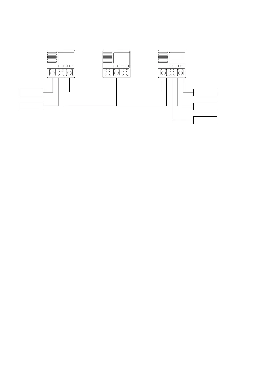
Interconnecting more Alarm Panels
40715
24V
24V
Interconnected panels Cable length < 200 meter
24V
24V
24V
24V
Inmarsat-C 1
VHF 1
Inmarsat-C 2
VHF 2
MF/HF
Alarm Panel 1 Alarm Panel 2 Alarm Panel 3
Up to 3 Alarm Panels can be interconnected and placed in different locations on the vessel.
Interconnected Alarm Panels maintain identical light and sound indications, so any operation
and behaviour on either Alarm Panel will be reflected on the others (except using the
Dimming button and the Test button – which only affects the single Alarm Panel being
dimmed or tested).
If interconnection is used, the combined set of Alarm Panels still only accepts the same 5
transceiver units, but each transceiver may be connected to either of the interconnected
Alarm Panels (e.g., the secondary VHF transceiver can be connected to the VHF 2 connec-
tor of any of the Alarm Panel).
The interconnection is physically established using a twisted pair cable. The interface is
electrically isolated and it must be supplied with 15V power to one of the Alarm Panels. The
15V interface power is taken from a dedicated supply available in the 9-pin power connector.
Note that only one of the interconnected Alarm Panels must supply the interface with power
in order to maintain the electrical isolation in the installation.