9
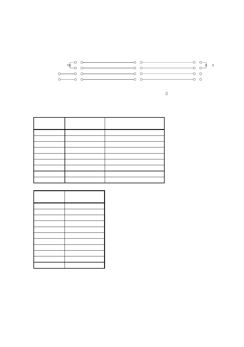
Wiring interconnected Alarm Panels
40714A
Alarm Panel 1 Alarm Panel 2 Alarm Panel 3
10
11
12
13
22
23
24
25
8
9
Option
DC Supply
Option Option
INTER S
INTER C
INTER H
INTER L
* 120
10
11
12
13
22
23
24
25
10
11
12
13
22
23
24
25
120
*
*
Note: The terminator resistor must match the cable used 120
is a typical value.
DC supply
D-sub 9 Designation
1ID-GND
2 S-RX SERVICE INTERFACE
3 S-TX SERVICE INTERFACE
4ID
5 GND SERVICE INTERFACE
6 DC- SUPPLY INPUT
7 DC+ SUPPLY INPUT
8 INTER-COUT INTERFACE SUPPLY OUT
9 INTER-SOUT INTERFACE SUPPLY OUT
Option
D-sub 25
1 and 14 AUX-TALKER B
2 and 15 AUX-TALKER A
3 and 16 AUX-TALKER C
5 and 18 AUX-LISTENER B
6 and 19 AUX-LISTENER A
7 and 20 AUX-LISTENER C
10 and 22 INTER L
11 and 23 INTER H
12 and 24 INTER C
13 and 25 INTER S
4.8.9 and 17 NC
Note 1: The denotion ”1 and 14”, “2 and 15” etc. used in the table indicates, that the two
pins are internally connected. This will ease cabling when the unit is not an
endpoint.
Note 2: The cable shield must be connected only to the Alarm Panel that powers the
interface (Alarm Panel 1 in the wiring diagram). All segments of the interface
cable must have connected shields”
0824