7
0824
Installation
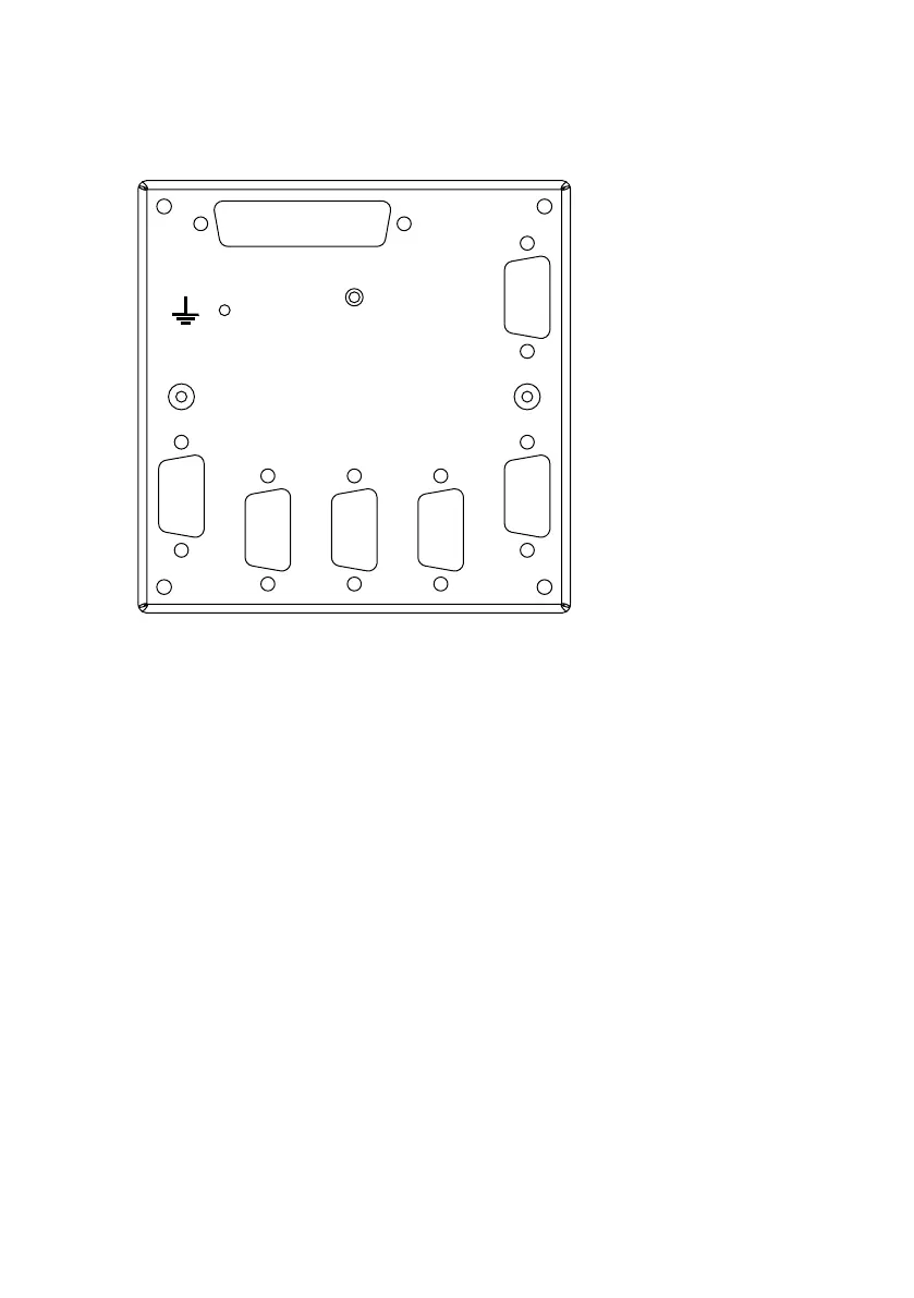
Connector overview
40708
Option
VHF 2
VHF 1
MF/HF
DC Supply
Inm-C 1
Inm-C 2
The Alarm Panel will connect to 5 transceiver units (2 × VHF, 2 × Inmarsat-C, and 1 × MF/
HF) each of which is provided a dedicated connector on the rear side of the Alarm Panel.
Auxiliary interfaces
The AP5065 Alarm Panel provides, through the option connector an auxiliary RS-422 line
with a separate Rx and Tx pair, that can be connected to external equipment for monitoring
of the Alarm Panel state. Unless specific installation instructions describes otherwise, this
interface should not be connected.
For further information please refer to Appendix A on page 16.
The power connector also provides a Service interface connection that may be used for
future maintenance of the Alarm Panel. Leave this disconnected for normal use.