5 CIRCUIT DESCRIPTION AND SCHEMATIC DIAGRAMS T2130
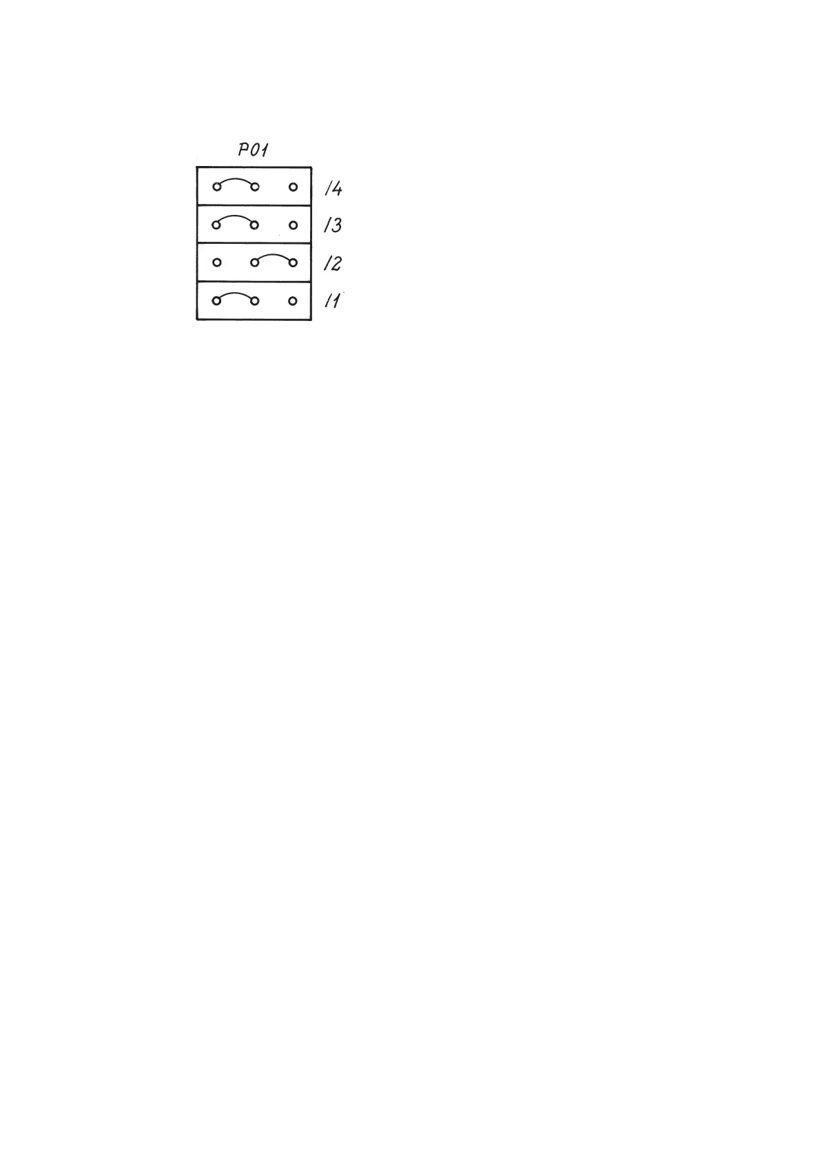
27C256 starts 8000 Hex:
Figure 3: P01 connections for 27C256.
26043 1/9
WATCH DOG & BATTERY LOW DETECTOR
The MAX 690 (U03) has the following purposes:
- ensures a proper reset for the microprocessor when the +5VB is stable
- senses the +18V (PFI, pin 4), and gives an early warning when the supply is failing. The limits for
the battery low detector are the following:
- The PFO (pin 5) must be high (+5V) at 17.231 Volt or higher on the +18V.
- The PFO must be low (0V) at 14.148 Volt or less on the +18V supply.
- Watch dog.
During normal operation the microprocessor resets the watch dog at known locations in the
programme.
If the microprocessor stays too long in an unintentional loop, without resetting the watch dog,
the watch dog will activate the reset pin on the microprocessor.
This may happen if the microprocessor is waiting for an external event which never occurs
(failure in hardware), or noise has disturbed the programme execution.
COMMUNICATION BUS DRIVER & RECEIVER (SP-BUS)
The communication to the RE2100 is time multiplexed data bus. It is implemented with one 50 ohm coax
cable terminated in each end and a driver and a receiver in each connected unit. The RE2100 is the master
and a number of slaves may be connected to the SP-Bus.
The driver and the receiver circuits are identical in each unit connected to the SP-Bus.
The driver output is normally in high impedance state except when transmitting on the
SP-Bus.
The driver consists of two gates, U04/1 & U04/2 (74HC132), a transistor Q01 (BC558) for level shifting
and two complementary output transistors Q02, Q03.
The driver is connected to the microprocessor U02, pin 13 (Port 2, bit 4, transmit data), and pin 10 (port
2, bit 1, driver enable).
The receiver consists of an op-amp, U06/1 (1458) which is configurated as a Schmitt Trigger and a gate
U05/1 (74HC08) for level conditioning.
The receiver is connected to the microprocessor U02, pin 12 (port 2, bit 3, receive data).
9737
PAGE 5-11
 Loading...