2 INSTALLATION MECHANICAL HF SSB TRANSMITTER T2130
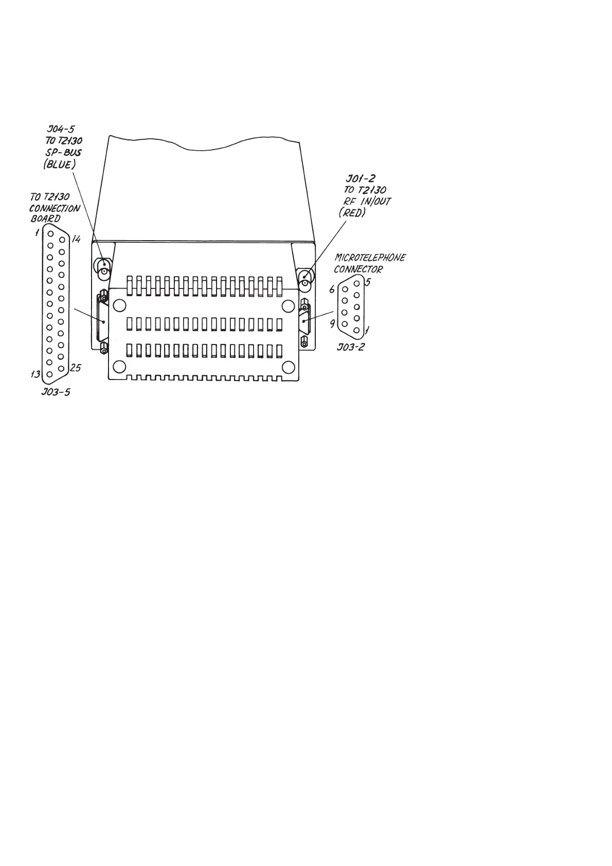
2.2.11 CONNECTIONS TO RE2100
25816
J03-5 J03-2
Pin no. 1 Mute RX Black Pin no. 1 Telephone Red
Pin no. 2 AF to AMP common Brown Pin no. 2 GND Yellow
Pin no. 3 Pin no. 3 Signal GND White
Pin no. 4 Pin no. 4 Mic Blue
Pin no. 5 GND Shield Pin no. 5 Mic key Brown
Pin no. 6 SP BUS interrupt Red Pin no. 6 Ext. SQ on/off
Pin no. 7 Orange Pin no. 7 Distress
Pin no. 8 Yellow Pin no. 8 Ser.+
Pin no. 9 AUX AF to TX common Green Pin no. 9 +18V
Pin no. 10 -18V Blue
Pin no. 11 +9V Violet
Pin no. 12 +18V Grey
Pin no. 13 Supply on/off White
Pin no. 14 Mic key Brown/pink
Pin no. 15 VF/AE-current Brown/yellow
Pin no. 16 AF to AMP Brown/green
Pin no. 17 0 dBm out common Brown/grey
Pin no. 18 0 dBm out White/pink
Pin no. 19 Ext. RF control White/yellow
Pin no. 20 AUX AF to TX White/green
Pin no. 21 RF on/off White/blue
Pin no. 22 GND White/grey
Pin no. 23 +9V Violet
Pin no. 24 +18V Grey/orange
Pin no. 25 -battery Red/blue
9315
PAGE 2-18
 Loading...