2 INSTALLATION RT2048
2.2. HANDSET
The handset can be placed anywhere near the VHF set. The cable is five-cored and connected to the rear
of the VHF through a 9-pole Sub-D connector.
Installation of the cable, see the drawings of the mounting brackets. The cable grommet must be placed
in the most convenient groove in the mounting bracket.
If more than one handset is needed, please see the section SPECIAL INSTALLATION WITH 2 OR 3
MICROTELEPHONES.
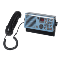
2.3. MICROTELEPHONE CONNECTOR
Pin No. 1 Telephone
Pin No. 2 GND
Pin No. 3 GND
Pin No. 4 Mic
Pin No. 5 Key
Pin No. 6 Spare
Pin No. 7 Distress CRY*
Pin No. 8 “Serial input”
25666 Pin No. 9 +13V internal
* only active when option board pcb is installed.
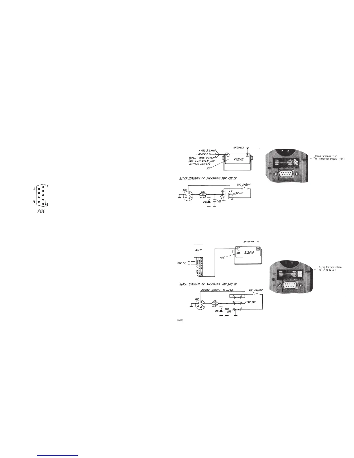
2.4. POWER SUPPLY
The standard power supply for RT2048 is 12V DC. For 24V DC supply an external power supply N420
(a 24V DC to 13.2V DC serial regulator) can be used.
For 110V AC, 127V AC, 220V AC, or 237V AC operation an external power supply N163S must be used
together with N420.
Page 2-6
9346
25664
25665