3 SERVICE RT2048
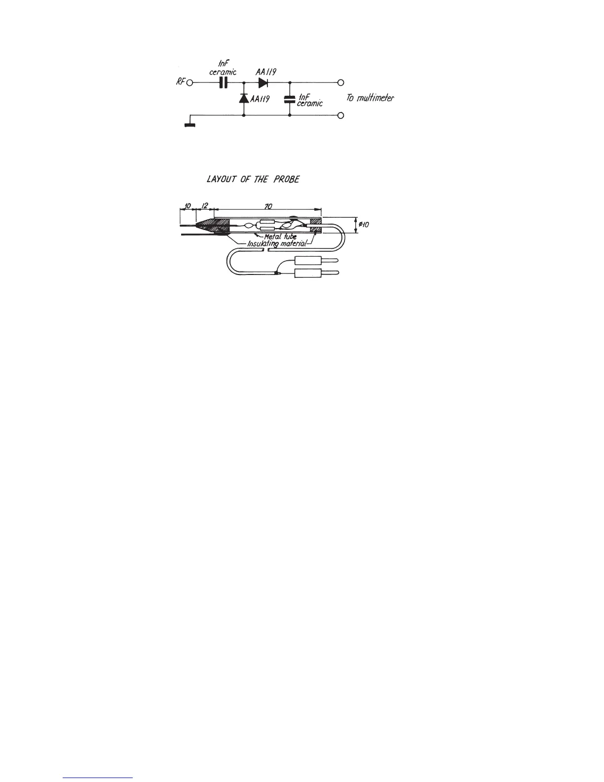
3.4. TEST PROBE
All measurings made by means of a test probe will be relative measurements. For quantitative measurings the diode
probe should be calibrated by means of a signal generator at a certain impedance level (50 ohm) as a function of
frequency.
3.5. ADJUSTMENT PROCEDURE
3.5.1. ADJUSTMENT OF SYNTHESIZER UNIT
Alignment of Frequency Generator and RF-levels
1. Connect a frequency counter to the TX-driver output of J4.
2. Select channel 6 and key the transmitter.
3. Connect a DC-voltmeter to the point between R50 and R95 and adjust 19 until the reading is 2.0V.
4. Adjust the frequency on C77 until the counter read-out is 156.300000 MHz ±150 Hz.
5. Connect a power meter to the TX-driver output at J4 and adjust the output level to minimum at R98.
6 Now the windings on coils L14, L13, and L12, L11, L10 are moved a little bit to obtain maximum
output at J4.
7. If the output level is below 200 mW, the level is raised by means of R98 until the power meter reading
is 200 mW.
8. Release the transmitter key; the set should still be on channel 6.
9. Connect a DC-voltmeter to the point between R50 and R95 and adjust C78 until the reading is 2.0V.
10. Check the RF-output level from the RX-buffer amplifier at J3. The level should be 5 mW -1 dB, +3 dB.
Alignment of Modulation Circuitry
1. Connect a modulation meter to the TX-driver output at J4, and a distortion meter to the AF-output part on
the modulation meter.
2. Connect tone generator and AF-voltmeter between pin 4 in the connector for handset and ground, pin 3.
3. Select channel number 6 and key the transmitter.
4. Turn potentiometer R97 fully clockwise.
5. Set the tone generator to a frequency of 1000 Hz and output level to 100 MVRMS.
6. Adjust R96 to nominal modulation: f = ±3 kHz and check that distortion is less than 5%.
7. Raise tone generator output level to 1.0 VRMS.
8. Adjust R97 to maximum deviation: f = ±4.8 kHz.
Alignment of RX-Filter Control Amplifier
1. The receiver must be tuned up according to the TUNE-UP PROCEDURE.
2. Select channel 28.
3. Connect signal generator to antenna connector J04.
4. Connect test probe to pin 16 at U03 on the RX/TX board.
5. Set signal generator frequency to 162.000. MHz and output level to -30 dBm.
6. Adjust R95 until maximum output level from the test probe is reached.
Page 3-2
RT2048A
4-0-25079