54
Installation
0611
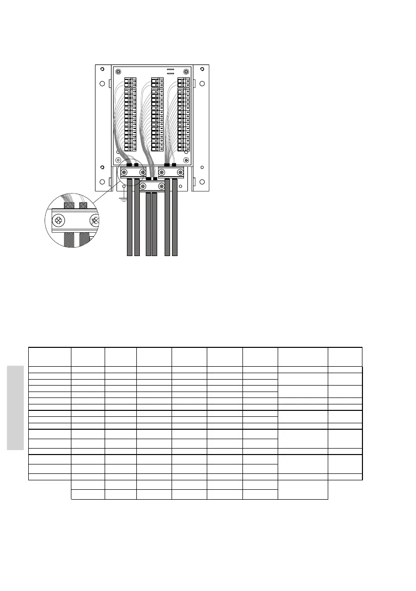
Cable connection diagram
39735
H1
H2
H3
H4
X1
X3
X2
X4
X5
X6
J2
J1
7
4
2
5
LS-
3
6
DATA-
1
12
13
15
14
11
LS+
X1
10
+12.5V
8
12
13
15
GND
14
11
7
3
10
6
Line out
1
5
2
4
X5
RX AF-
X6
X4
9
8
Line out
9
+12.5V
GND
RX AF+
TX AF-
TX AF+
CU/CB
VHF
CU
+12.5V
DATA+
X6 :
X3
X2
12
13
15
14
10
EXT LS+
EXT LS-
CU LS+
CU LS-
EXT/CU
LS-
EXT/CU
LS+
J1 & J2 MOUNTED = EXT LS
J1 & J2 NOT MOUNTED = CU LS
VHF DSC
CU 1 (Optional)
Ext. speaker (CU)
CU 2 (Optional)
Ext. speaker (CU2)
Ext. speaker (VHF)
VHF Signal Cable Extension box Extension box Cable integrated Extension box Signal description Ships cable
SPARC II connecto
designation p/n 56.114 In from VHF Out to CU1 with CU Out to CU2 8 twisted pairs
15-pin D-sub female
or conn. Box overall screen
pin 1 12.5VDC+ Red/Wht X2-1 X1-1 Red/Wht X3-1 Power to CUs pair no. 8
pin 2 DATA_+ Yel X2-2 X1-2 Yel X3-2 pair no. 1
pin 3 DATA_- Yel/Blk X2-3 X1-3 Yel/Blk X3-3 pair no. 1
pin 4 TX_AF+ Blue/Wht X2-4 X1-4 Blu/Wht X3-4 pair no. 2
pin 5 TX_AF- Blue X2-5 X1-5 Blu X3-5 pair no. 2
pin 6 GND Orange + Red X2-6 X1-6 Orange + Red X3-6 Equipment ground pair no. 6 & 8
pin 7 12.5VDC+ Orange/Wht X2-7 X1-7 Orange/Wht X3-7 Power to CUs pair no. 6
pin 8 RX_AF+ Green/Wht X2-8 X1-8 Grn/Wht X3-8 pair no. 3
pin 9 RX_AF- Green X2-9 X1-9 Grn X3-9 pair no. 3
pin 10 12.5VDC+ Blk/Wht X2-10 X1-10 Blk/Wht X3-10 Power to CUs pair no. 7
pin 11 EXT.Speaker + Brown X2-11 X1-11 Brn X3-11 pair no. 4
pin 12 EXT.Speaker - Brown/Wht X2-12 X1-12 Brn/W ht X3-12 pair no. 4
pin 13 GND Blk X2-13 X1-13 Blk X3-13 Equipment ground pair no. 7
pin 14 Lineout + Purple X2-14 X1-14 Purple (
NC
) X3-14 pair no. 5
pin 15 Lineout - Purple/Wht X2-15 X1-15 Purple/Wht (
NC
) X3-15 pair no. 5
Housing Screen Chassis Chassis Screen Chassis Screen
EXT LS
(VHF LS out: X5-1) CU1 LS out: X4-1 CU2 LS out: X6-1
EXT LS
(VHF LS out: X5-2) CU2 LS out: X4-2 CU2 LS out: X6-2
Connecting only one CU (CU1) and leaving jumpers J1/J2 in circuit provides VHF Ext. Speaker connection available at both X5-1/2 and X6-1/2.
VHF Ext. Speaker output will be available at terminals X5-1/2.
Rx-audio line output,
balanced signal, 0dBm
into 600Ω
External speaker
output, nom. 5W into
8Ω (
se e NOTE
)
NOTE:
In case of connecting a second CU (CU2) to the Extension Box, jumpers J1/J2 should be removed in order to disconnect VHF
Ext. Speaker (VHF LS) output from terminals X6-1/2 and make available the CU2 Ext. Speaker (CU2 LS) connections instead.
SPARC II-bus Data
SPARC II-bus Tx audio
SPARC II-bus Rx audio
VHF radio external
speaker output, nom.
5W into 8Ω