53
Installation
0645
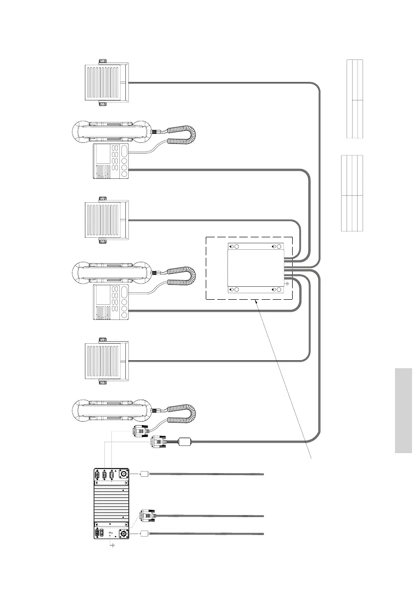
9.3.2 System block diagram with extension box
SPARC II bus
Handset
(Optional) (Optional)
Ext. speaker (CU1)
Ext. speaker (CU2)
CU 1 (Optional)
39702D
CU 2 (Optional)
(Optional)
Ext. speaker (VHF)
(Optional)
Extension Box
Note:
SPARC II cable length specification
Conductor size
Maximum cable length
8x2x0.5mm2
20m
8x2x0.75mm2
30m
8x2x1mm2
40m
All cabling not furnished with equipment to be overall screened type.
Cable screens must be securely grounded at cable inlets in connection boxes,
120W min. continuous
Power cable p/n 539826, 1.5m 2x4.0mm2
+ VDC
White or red
0 VDC
Black
(rear view)
56.114
L=5m
VHF
DSC Antenna
RG214 or better
PL259
RX/TX Antenna
RG214 or better
PL259
Power
12-24V DC
Cable part no. 539826
L=1.5m
furnished with equiptment
L=3m
Cable Connection diagram
See next page:
Power connection 12-24VDC,
External power supply input is galvanically isolated from equipment ground reference, i.e. chassis.
Equipment internal power supply reference (-) is at equipment ground reference, i.e. chassis.
as illustrated in cable connection diagrams.
L=3m
(150W min. for RT5020)
 Loading...