PDM20 Series
-17-
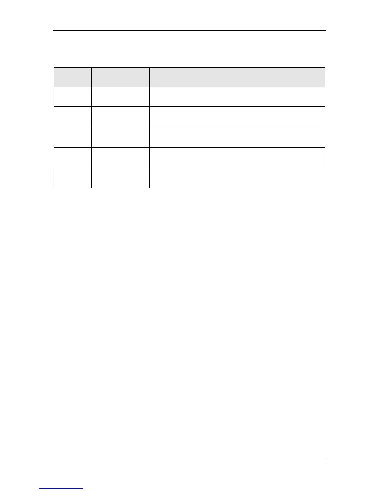
2.6.2 Terminal instruction
Terminal
symbol
Terminal name Technical data
M1
Multi-function
input terminal 1
Enabled when connected to GND; Disabled when open
M2
Multi-function
input terminal 2
Enabled when connected to GND; Disabled when open
AI
Analog input
terminal 1
It is 0 ~ 10V analog voltage input terminal or 4-20mA
analog current input terminal, chosen by function codes.
+Vo
Positive terminal
of analog power
+5V~+24V adjustable power; Output voltage value is set
by function codes.
GND
Negative terminal
of analog power
Reference zero potential of +5V~+24V adjustable power
2.7 Wiring of Sensors
2.7.1 Terminal instruction
◆
+VO ---5
~
24V Power terminal for transmissible pressure gauge/pressure
transmitter
◆
AI ---0
~
10V analog signal input terminal (voltage feedback type) or 4
~
20mA
signal input terminal (current feedback type)
◆
GND --- 5
~
24V signal common terminal
2.7.2 Sensor configuration instruction
A current type pressure sensor will be used by default; output signal is 4~20mA. If
use other types of sensors, please refer to the setting parameters P0.03
,
P0.04
,
P0.05 in Chapter 4.5.
2.7.3 Wiring diagram
The drive can be connected to transmissible pressure gauge and pressure
transmitter. Please connect wire according to below diagrams.
 Loading...