Do you have a question about the Sakai SV544 and is the answer not in the manual?
Covers machine movement, parking, chocks, and hazardous area safety precautions.
Details safety measures for hydraulic systems, engine starting, and compartment inspections.
Covers model, type, displacement, speed, output, torque, and fuel consumption.
Lists oil types, grease, fuel, DEF, and their applicable standards.
Details capacities for engine oil pan, fuel tank, coolant, and other fluid reservoirs.
Details relief valve settings, case pressure, and drainage for the propulsion system.
Specifies relief valve settings, case pressure, and drainage for the vibration system.
Covers brake release pressure and steering oil pressure specifications.
Identifies air cleaner and DEF tank filter assemblies and elements.
Covers hydraulic and fuel filter assemblies and their elements.
Details the engine oil filter element.
Identifies and describes console controls, switches, and levers.
Explains dashboard meters, warning lamps, and indicator lights.
Lists and describes the various indicators on the combination meter.
Details the pinout for the harness side connector.
Identifies ECO controller, relays, and fuses within the electrical box.
Highlights diagnostic and service tool connection points.
Lists and describes the functions of various relays (B-series, A-series).
Covers fuse ratings and spare locations within the fuse box.
Identifies battery relay, starter relay, and main fuses for the power system.
Provides a schematic of the battery and starter circuit.
Explains fault code messages and the diagnostic process.
Refers to a separate manual for detailed engine troubleshooting.
Describes normal and abnormal status indications by LED lights.
Details error codes, descriptions, and bypass actions for the ECO controller.
Covers display, park brake, neutral, and battery voltage checks.
Details steps for checking the starter, relays, and fuses.
Identifies locations of starter lockout, neutral safety, and park brake relays/fuses.
Points out ECM fuse, battery relay, and starter relay locations.
Illustrates power flow from battery through key switch and relays to starter.
Shows how neutral, park brake, and starter relays interact with switches.
Guides through checking engine codes and fuel levels in the machine.
Details checks at filters and fuel pump for fuel presence.
Covers unloader valve, parking brake, and drive cable issues.
Guides through brake switch, solenoid, and relay checks.
Shows wiring for brake switches, solenoids, and relays.
Identifies brake switches, solenoids, and the brake release valve.
Details steps for measuring propulsion circuit pressure.
Explains how to adjust pressure and lists torque specifications.
Outlines steps for measuring propulsion motor pressure.
Specifies the standard value for the flushing relief valve.
Guides through checking the drum speed change solenoid and fuse F6.
Covers checks for the speed select switch and solenoid magnetization.
Explains the travel mode switch and available speed ranges.
Describes how slope operation is selected within travel modes.
Details wiring for rabbit speed solenoids and mode switches.
Shows how speed change switch positions map to terminals.
Covers issues with vibration in one direction or switch functionality.
Guides through ECO controller and solenoid checks for vibration.
Explains how the main vibrator switch controls amplitude and On/Off.
Details the function of the vibration selector switch on the F-N-R lever and panel.
Details pin assignments and connections for the ECO controller.
Illustrates wiring for vibrate solenoids and associated switches.
Outlines steps for measuring vibrator circuit pressure.
Details inspection, cleaning, and replacement of the high pressure relief valve.
Details steps for measuring vibrator charge circuit pressure.
Explains adjustment of the charge relief valve and its setting.
Lists AC capacity and important safety precautions for handling refrigerant.
Identifies key components of the AC system, including control panel and internal parts.
Details circuit breakers and DC power inputs for the AC system.
Shows wiring for fan switch, thermostat, compressor, and motors.
| Brand | Sakai |
|---|---|
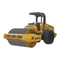
| Model | SV544 |
| Category | Construction Equipment |
| Language | English |