EasyManua.ls Logo

Sakai SW352 - User Manual

Default Icon
176 pages
Print Icon
To Next Page IconTo Next Page
Loading...
PREFACE
Generally, rollers tend to come large-sized and find their applications in
dangerous fields such as rough terrain, steep slopes or slippery areas. Faulty
rollers may risk a grave accident.
For purpose-built rollers to negotiate problem terrain with the ultimate in
performance maintained free from failure over the longest possible period of
time, adequate handling and regular preventive maintenance recommended
are of prime importance. If a trouble developes, it should be effectively
corrected with proper safety measures taken.
This service manual is intended to serve as a guide particularly for
maintenance personnel to perform quality service by gaining working
knowledge of and reliable maintenance techniques for machines in question.
Included in this literature are descriptions of SPECIFICATIONS, STRUCTURE
& OPERATION, INSPECTION & ADJUSTEMNT, FAULT DIAGNOSIS and
DISASSEMBLY & ASSEMBLY. Systematic explanations are being given to
each of these five cathegories in this sequence.
Rollers principally concern qualitative factors as represented by ‘compaction
density’, to say nothing of quantitative elements like ‘productivity’.
SPECIFICATIONS section includes performance data of major significance
e.g. ‘vibratory frequency’ to be checked when servicing machines in question.
For reasonable maintenance services, it is a precondition to know the vital
portions of machines in question and how they work. Referring to relevant
electric wiring and hydraulic circuit diagrams, STRUCTURE & OPERATION
instructs location of key units and function of systems into which the key units
are assembled.

Table of Contents

Question and Answer IconNeed help?

Do you have a question about the Sakai SW352 and is the answer not in the manual?

Summary

PREFACE

SPECIFICATIONS

1. External Views and Specification Data

Provides diagrams and data for different machine models, including dimensions, weight, and performance.

1-1. SW352

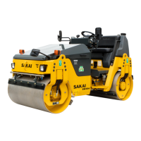
Details external views and specification data for the SW352 model.

1-2. TW352

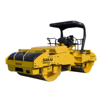
Details external views and specification data for the TW352 model.

1-3. SW502

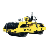
Details external views and specification data for the SW502 model.

1-4. TW502

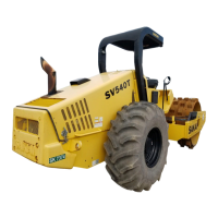
Details external views and specification data for the TW502 model.

STRUCTURE AND OPERATION

1. Location of Engine-related Units

Illustrates and identifies various engine components and their locations on the machine.

2. Description and Operation of Hydraulic System

Explains the hydraulic system, including pumps, motors, and circuit diagrams.

2-1. Hydraulic pump

Describes the propulsion pump assembly and its technical data for different models.

2-2. Propulsion line

Details the hydraulic piping and components of the propulsion system.

2-3. Vibrating system

Explains the hydraulic piping and circuits for the vibrating system.

2-4. Steering system

Covers hydraulic piping, steering valve, and cylinder for the steering system.

2-5. Brake System

Describes the brake pedal and parking brake circuit operation.

2-6. Electric System

Locates instrument panel components and key electrical units.

INSPECTION AND ADJUSTMENT

1. Standard Value Chart

Provides standard values for engine, travel speed, and hydraulic oil pressure.

1-1. SW352, TW352

Lists standard values for SW352 and TW352 models for inspection.

1-2. SW502, TW502

Lists standard values for SW502 and TW502 models for inspection.

2. Inspection and Adjustment

Details procedures for measuring and adjusting various circuit pressures and linkages.

2-1. Measurement and adjustment of pressure in propulsion main circuit

Outlines steps for measuring and adjusting propulsion main circuit pressure.

2-2. Measurement and adjustment of propulsion charge circuit pressure

Details procedures for measuring and adjusting propulsion charge circuit pressure.

2-3. Measurement of propulsion motor speed selecting pressure

Explains how to measure propulsion motor speed selecting pressure.

2-4. Measurement of brake release pressure

Describes the process for measuring brake release pressure.

2-5. Measurement of vibrator circuit pressure

Details how to measure vibrator circuit pressure.

2-6. Measurement and adjustment of steering circuit pressure

Outlines procedures for measuring and adjusting steering circuit pressure.

2-7. Throttle linkage adjustment

Explains how to adjust the throttle linkage for correct RPM.

2-8. Adjustment of F-R lever linkage stroke

Guides the adjustment of the F-R lever linkage stroke for smooth operation.

FAULT DIAGNOSIS

1. Precautions for Fault Diagnosis

Provides safety guidelines and general advice before performing fault diagnosis.

2. How to Make a Fault Diagnosis

Outlines the step-by-step process for making a fault diagnosis.

3. How to Use Fault Diagnosis Flow Chart

Explains how to interpret and use fault diagnosis flow charts.

4. Precautions for Fault Diagnosis of Electric System

Offers specific safety and procedural advice for diagnosing electric system faults.

5. Fault Diagnosis of Electric System (Mode E)

Provides troubleshooting procedures for various electric system faults.

6. Fault Diagnosis of Hydraulic and Mechanical Systems (Mode H)

Offers troubleshooting steps for hydraulic and mechanical system issues.

DISASSEMBLY AND ASSEMBLY

Precautions for Work

General safety guidelines and precautions for disassembly and assembly procedures.

1. Removal and Installation of Alternator Assembly

Details the procedure for removing and installing the alternator assembly.

2. Removal and Installation of Starter Assembly

Outlines the steps for removing and installing the starter assembly.

3. Removal and Installation of Radiator;Oil Cooler Assembly

Explains how to remove and install the radiator and oil cooler assembly.

4. Removal and Installation of Engine and Propulsion;Vibration;Steering;Charge Pump Assembly

Covers the removal and installation of the engine and associated pump assemblies.

5. Removal and Installation of Coupling

Details the procedure for removing and installing the coupling.

6. Removal and Installation of Front Drum Assembly

Explains how to remove and install the front drum assembly.

7. Disassembly and Assembly of Front Drum Assembly

Provides detailed steps for disassembling and assembling the front drum.

8. Removal and Installation of Center Pin Assembly

Outlines the process for removing and installing the center pin assembly.

9. Removal and Installation of Rear Propulsion Motor Assembly and Wheels (TW352, TW502)

Covers removing and installing the rear propulsion motor and wheels.

10. Removal and Installation of Propulsion;Vibration;Steering;Charge Pump Assembly (SW352, SW502)

Details removing and installing the main pump assemblies for specific models.

11. Removal and Installation of Vibrator Pump Assembly (SW352, SW502)

Explains how to remove and install the vibrator pump assembly.

12. Removal and Installation of Vibrator Motor Assembly

Outlines the procedure for removing and installing the vibrator motor assembly.

13. Disassembly and Assembly of Propulsion Motor Negative Brake

Provides steps for disassembling and assembling the propulsion motor's negative brake.

14. Removal and Installation of Steering Cylinder Assembly

Details the process for removing and installing the steering cylinder.

15. Disassembly and Assembly of Steering Cylinder Assembly

Explains how to disassemble and assemble the steering cylinder.

16. Removal and Installation of Steering Wheel

Covers the removal and installation of the steering wheel.

17. Removal and Installation of Orbitrol

Outlines the procedure for removing and installing the Orbitrol unit.

Sakai SW352 Specifications

General IconGeneral
BrandSakai
ModelSW352
CategoryConstruction Equipment
LanguageEnglish

Related product manuals