Do you have a question about the Sakai SW354 and is the answer not in the manual?
Covers understanding safety symbols, words, general safety practices, and qualifications for personnel.
Details daily checks, ensuring all stickers are in place, and knowing emergency shutdown procedures.
Provides precautions for safe operation, avoiding unsafe modes, and using machine access points.
Instructions for safely starting the machine, including seat belt use and checking indicators.
Guidelines for safe operation, including obstructions, climbing, traffic regulations, and load stability.
Procedures for safely parking the machine, including neutral position, parking brake, and compartment locking.
Safety precautions for all maintenance, inspection, and repair work, including area safety and securing the machine.
Guidelines for safe loading, unloading, and securing the machine for transport, including vehicle compatibility and traffic regulations.
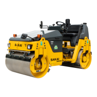
Detailed technical specifications including weight, dimensions, and drum/tire details for SW354.
Technical specifications for SW354 with ROPS, covering weight, dimensions, and drum details.
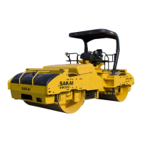
Technical specifications for TW354, including weight, dimensions, and tire/drum details.
Technical specifications for TW354 ROPS, covering weight, dimensions, and tire/drum details.
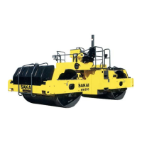
Technical specifications for TW504, including weight, dimensions, and drum/tire details.
Technical specifications for TW504 ROPS, covering weight, dimensions, and tire/drum details.
General specifications for engine, drive system, brakes, steering, drums, tires, and sprinkler system.
Standard values for engine parameters including model, output, torque, and clearances.
Standard values for propulsion system including travel speed, hub bolt torque, and tire inflation pressure.
Standard values for hydraulic system parameters like pressure settings and case pressure.
Standard values for steering system, including play in steering wheel and column shaft direction.
Standard values for brake system, including pedal clearance and replacement standard brake stroke length.
Fluid capacities for engine oil, fuel tank, hydraulic oil, vibrator case, water spray tank, and liquid spray tank.
Specifications for fuel and lubricants, including service classification and applicable standards for various temperatures.
Recommendations for engine oil, gear oil, hydraulic oil, and grease from various oil companies.
Chart detailing tightening torques for various metric screws based on nominal diameter, pitch, and strength classification.
Detailed illustration and parts list for the engine mounting components.
Illustration and parts list for the throttle control system.
Illustration and parts list for the forward-reverse control mechanism.
Illustration and parts list for the pump mount.
Procedure for installing the pump assembly, including grease application and securing bolts.
Detailed illustration and parts list for the engine mounting components specific to SW504.
Illustration showing the fuel system components and their layout for SW504.
Illustration and parts list for the throttle control system specific to SW504.
Illustration and parts list for the forward-reverse control mechanism specific to SW504.
Illustration and parts list for the pump mount specific to SW504.
Illustrations and descriptions of basic symbols and symbols for pumps, motors, cylinders, and valves.
Schematic diagram illustrating the hydraulic circuit for SW354.
Schematic diagram illustrating the hydraulic circuit for TW354.
Schematic diagram illustrating the hydraulic circuit for TW504.
Diagrams showing propulsion hydraulic piping for SW/TW354.
Diagram illustrating the propulsion hydraulic piping (F) for TW504.
Diagram illustrating the propulsion hydraulic piping (R) for SW354.
Diagram illustrating the propulsion hydraulic piping (R) for TW354.
Diagram illustrating the propulsion hydraulic piping (R) for TW504.
Specifications for the propulsion hydraulic pump, including port identification and performance data.
Specifications for the propulsion hydraulic motor (F) for SW/TW354, including displacement and pressure ratings.
Specifications for the propulsion hydraulic motor (F) for TW504, including displacement and pressure ratings.
Specifications for the propulsion hydraulic motor (R) for SW354, including displacement and pressure ratings.
Specifications for the propulsion hydraulic motor (R) for TW354,504, including displacement and pressure ratings.
Specifications for the differential lock valve (TW354,504), including flow, pressure, and weight.
Diagrams showing the vibrator hydraulic piping for SW354.
Diagram illustrating the vibrator hydraulic piping for TW354.
Diagram illustrating the vibrator hydraulic piping for TW504.
Specifications for the hydraulic pump assembly (vibrator (F) + steering • charge), including displacement and rated pressure.
Specifications for the vibrator hydraulic pump (R) for SW354, including displacement and rated pressure.
Specifications for the vibrator hydraulic motor, including displacement and rated pressure.
Specifications for the cooling fan drive hydraulic motor, including displacement, rated pressure, and relief valve settings.
Specifications for vibrator solenoid valves (F) and (R) for SW/TW354, including flow, pressure, and weight.
Specifications for vibrator solenoid valve for TW504, including rated flow, pressure, and weight.
Diagrams showing the steering hydraulic piping for SW/TW354.
Diagram illustrating the steering hydraulic piping for TW504.
Illustration and specifications for the steering wheel assembly, including nut and bolt torque values.
Specifications for the Orbitrol component, including displacement, pressure, and weight.
General precautions for working with electrical systems, including wire codes and connector handling.
Electrical circuit diagram for SW354, showing component connections and wire routing.
Electrical circuit diagram for SW354 ROPS, detailing component connections and wire routing.
Electrical circuit diagram for TW354, illustrating component connections and wire routing.
Electrical circuit diagram for TW354 ROPS, showing component connections and wire routing.
Electrical circuit diagram for TW504, detailing component connections and wire routing.
Electrical circuit diagram for TW504 ROPS, illustrating component connections and wire routing.
Layout of wiring harnesses for SW354, showing component connections and routing.
Second part of the wiring harness layout for SW354, detailing connections and routing.
First part of the wiring harness layout for TW354, showing component connections and routing.
Second part of the wiring harness layout for TW354, detailing connections and routing.
Wiring harness layout for TW504, showing component connections and routing.
First part of the wiring harness layout for TW504, detailing connections and routing.
Second part of the wiring harness layout for TW504, showing component connections and routing.
Diagram and specifications for the engine harness, detailing connections and part numbers.
Diagram and specifications for the dashboard harness (1), showing connections and routing.
Diagram and specifications for the frame (F) harness (SW/TW354), detailing connections.
Diagram and specifications for the frame (F) harness (TW504), detailing connections.
Diagram and specifications for the frame (R) harness.
Diagram and specifications for the stater switch harness.
Diagram and specifications for the control switch harness.
Diagram and specifications for the working switch harness (except ROPS).
Diagram and specifications for the working switch harness (ROPS).
Diagram and specifications for the parking brake switch harness.
Diagram and specifications for the short harness (SW/TW354, except SW354 ROPS).
Diagram and specifications for the vibration Lo-Hi change switch harness (TW504).
Diagram and specifications for the vibrator solenoid (R) harness (SW354).
Diagram showing the cap for TW354,504.
Diagram showing the cap for the hazard switch harness (except ROPS).
Diagram and specifications for the hazard switch harness (ROPS).
Diagram and specifications for the Mihaalu harness.
Diagram and specifications for the liquid spray switch harness (TW354,504).
Diagram and specifications for the liquid spray pump harness (TW354,504).
Diagram and specifications for the short harness.
Diagram and specifications for the vibratory drum select switch harness (SW354 ROPS).
Diagram and specifications for the F-R lever vibration switch (L) harness.
Diagram and specifications for the F-R lever vibration switch (R) harness.
Specifications for the fuse box of SW354, including fuse ratings and connected components.
Specifications for the fuse box of TW354, including fuse ratings and connected components.
Specifications for the fuse box of TW504, including fuse ratings and connected components.
Diagram and system configuration for the combination meter.
Electrical circuit diagram for SW504, showing all connections and components.
Electrical circuit diagram for models without ROPS.
Layout of wiring harnesses for SW504, showing component connections and routing.
Second part of the wiring harness layout for SW504, detailing connections and routing.
Diagram and specifications for the engine harness, detailing connections and part numbers.
Diagram and specifications for the dashboard harness (1).
Diagram and specifications for the dashboard harness (2).
Diagram and specifications for the ECU harness (Vehicle).
Diagram and specifications for the ECU harness (Engine).
Diagram and specifications for the Frame (F) Harness.
Diagram and specifications for the Frame (R) Harness.
Diagram and specifications for the Stater Switch Harness.
Diagram and specifications for the Control Switch Harness.
Diagram and specifications for the Working Switch Harness (ROPS).
Diagram and specifications for the Working Switch Harness (except ROPS).
Diagram and specifications for the Vibration Switch Harness (ROPS).
Diagram and specifications for the Vibration Lo-Hi change switch harness (except ROPS).
Diagram and specifications for the Vibrator Solenoid (F) Harness (1).
Diagram and specifications for the Vibrator Solenoid (F) Harness (2).
Diagram and specifications for the Vibrator Solenoid (R) Harness (1).
Diagram and specifications for the Vibrator Solenoid (R) Harness (2).
Diagram and specifications for the Vibrator Solenoid (R) Harness (3).
Diagram and specifications for the Vibrator Solenoid (R) Harness (4).
Diagram and specifications for the Hazard Switch Harness (ROPS).
Diagram showing the cap for the Hazard Switch Harness (except ROPS).
Diagram and specifications for the DPF Switch Harness.
Diagram and specifications for the Diagnostic Switch Harness.
Diagram and specifications for the Parking Brake Switch Harness.
Diagram and specifications for the Mihaalu Harness.
Diagram and specifications for the Starter Relay Harness.
Diagram and specifications for the F-R Lever Vibration Switch (L) Harness.
Diagram and specifications for the F-R Lever Vibration Switch (R) Harness.
Diagram and specifications for the Short Harness.
General precautions for disassembly, installation, and reassembly of the unit.
Procedure for removing and installing the vibratory drum assembly.
Detailed illustration and parts list for the vibratory drum assembly (SW/TW354).
Detailed illustration and parts list for the vibratory drum assembly (TW504).
Step-by-step procedure for disassembling the vibratory drum.
Procedure for reassembling the vibratory drum, including cleaning parts and applying grease.
Illustration and specifications for the rear axle assembly (TW types).
Procedures for removing and installing the rear axle assembly (TW types).
Steps for removing the rear axle, including supporting the frame and removing bolts.
Procedure for installing the rear axle, including tightening torques and fluid level checks.
Reference to procedures for removing and installing the vibratory drum for SW504.
Reference to procedures for disassembling and reassembling the vibratory drum.
Illustration and parts list for the brake pedal assembly.
Hydraulic schematic for the brake system of SW354, showing components and flow direction.
Hydraulic schematic for the brake system of TW354, 504, showing components and flow direction.
Diagrams illustrating the water spray piping for SW354, including ports and components.
Diagrams illustrating the water spray piping for TW354,504, including ports and components.
Diagrams illustrating the liquid spray piping for TW354,504, including ports and components.
Safety warnings and precautions for conducting inspections and adjustments on the machine.
Steps for preparing inspection and adjustment procedures, including instrument selection and verification.
General precautions for performing inspections and adjustments, emphasizing safety and measurement accuracy.
Procedure for warming up the engine and ensuring fluids reach normal operating temperatures before measurements.
Reference to the engine manufacturer's shop manual for engine-specific inspection and adjustment procedures.
Procedure for measuring and inspecting the propulsion circuit pressure.
Detailed steps for measuring propulsion circuit pressure, including safety warnings and instrument setup.
Inspection procedures for the propulsion circuit pressure if measurement results deviate from standard.
Procedure for measuring and adjusting the propulsion charge circuit pressure.
Steps for measuring propulsion charge circuit pressure, including safety warnings and temperature checks.
Procedure for adjusting the charge relief pressure if it deviates from the standard setting range.
Procedure for measuring high/low speed change circuit pressure for SW504.
Procedure for measuring parking brake release pressure for SW types (front and rear) and TW types (front).
Detailed steps for measuring parking brake release pressure, including safety warnings and temperature checks.
Procedure for measuring parking brake release pressure for TW types (rear).
Procedure for measuring vibrator circuit pressure for SW504, including safety warnings and temperature checks.
Procedure for measuring and inspecting steering circuit pressure for SW504, including safety warnings.
Inspection procedure for the steering circuit pressure if measurements deviate from standard.
Procedure for measuring the propulsion pump case pressure, including safety warnings and temperature checks.
Procedure for adjusting the throttle lever potentiometer and operating force for SW504.
Steps for adjusting the potentiometer, including setting throttle lever positions and engine speeds.
Procedure for adjusting the operating force of the throttle lever knob and lever to standard values.
Procedure for adjusting the F-R lever linkage for SW504, including specified dimensions.
Steps for adjusting the F-R lever linkage, control cable, and confirming propulsion pump strokes.
Procedure for adjusting the operating force of the F-R lever knob to standard values.
Procedure for measuring brake piston stroke quantity as a replacement standard.
Procedure for measuring propulsion circuit pressure for SW504, including safety warnings and temperature checks.
Detailed steps for measuring propulsion circuit pressure, ensuring safety and proper gauge connection.
Inspection procedure for propulsion circuit pressure if measurement results deviate from standard.
Procedure for measuring and adjusting propulsion charge circuit pressure for SW504.
Steps for measuring propulsion charge circuit pressure, including safety warnings and temperature checks.
Procedure for adjusting the charge relief pressure if it deviates from the standard setting range for SW504.
Procedure for measuring machine high/low speed change circuit pressure for SW504.
Procedure for measuring vibrator circuit pressure for SW504, including safety warnings and temperature checks.
Procedure for measuring and inspecting steering circuit pressure for SW504, including safety warnings.
Inspection procedure for steering circuit pressure if measurements deviate from standard.
Procedure for measuring hydraulic pump case pressure for SW504, including safety warnings and temperature checks.
Procedure for adjusting the throttle lever potentiometer and operating force for SW504.
Steps for adjusting the potentiometer, including setting throttle lever positions and engine speeds.
Procedure for adjusting the operating force of the throttle lever knob to standard values for SW504.
Procedure for adjusting the F-R lever linkage for SW504, including specified dimensions.
Safety warnings and precautions for performing troubleshooting procedures.
Guidance on understanding systems, identifying causes, and performing troubleshooting effectively.
Steps to follow before starting troubleshooting, including studying manuals and checking with the operator.
Precautions to take when diagnosing electrical system faults.
Specific precautions for disconnecting/connecting connectors, checking for faulty connections, and grounding.
General procedures for inspecting circuits using a tester, including measuring resistance and voltage.
Steps for inspecting the electrical system, including checking relays, fuses, connectors, and harness.
Troubleshooting steps for when the engine will not start and the starter motor does not run.
Continuation of troubleshooting steps for engine start issues, focusing on relays and switches.
Final steps for troubleshooting engine start issues, including neutral relay and harness checks.
Troubleshooting steps when the starter motor runs but the engine will not start, focusing on fuel supply.
Troubleshooting steps for when the engine does not stop running.
Troubleshooting steps for when the charging system is not functioning.
Troubleshooting steps for when glow plugs are not heated, affecting cold weather starting.
Troubleshooting steps for when the machine fails to move forward or backward.
Detailed checks for propulsion issues, including oil level, bypass valve, linkage, and pressure.
Troubleshooting steps for when the machine speed cannot be changed.
Troubleshooting steps for when the brake cannot be released.
Troubleshooting steps for when the brake system is not functioning.
Troubleshooting steps for when no vibration occurs.
Detailed checks for vibrator solenoid, mode select switch, and drum select switch.
Continuation of troubleshooting for no vibration, covering Lo-Hi change switch and vibrator relay.
Troubleshooting for when vibration mode cannot be switched due to F-R lever vibration switch issues.
Troubleshooting steps for when the vibratory drum cannot be switched on SW354 ROPS models.
Troubleshooting for when amplitude does not change, remaining low or high on TW504 models.
Troubleshooting steps when continuous water spray does not operate.
Checks for battery, water spray pump, relay, and mode select switch.
Troubleshooting steps when continuous water spray works, but auto water spray does not operate.
Troubleshooting steps when liquid cannot be sprayed on TW354, 504 models.
Troubleshooting steps when head lamps and tail lamps do not light.
Checks for battery, bulbs, lighting switch, and harness connections.
Troubleshooting steps when the flood lamp does not light.
Troubleshooting steps when the turn signal lamp does not blink.
Troubleshooting steps when hazard lamp does not light (Turn signal blinks) on ROPS type.
Troubleshooting steps when the stop lamp does not light.
Troubleshooting steps when the combination meter illumination does not light.
Troubleshooting steps when combination meter warning or indicator lamps are abnormal.
Troubleshooting steps for abnormal tachometer readings.
Troubleshooting steps for when the hour meter is abnormal.
Troubleshooting steps for abnormal temperature meter readings.
Troubleshooting steps for when the fuel meter is abnormal.
Troubleshooting steps when the hydraulic oil filter warning lamp remains ON.
Troubleshooting steps when the charge warning lamp remains ON.
Troubleshooting steps when the engine oil pressure warning lamp remains ON.
Troubleshooting steps when the vibration indicator lamp does not light.
Troubleshooting steps when the water spray indicator lamp does not light.
Troubleshooting steps when the liquid spray indicator lamp does not light for TW354, 504.
Troubleshooting steps when the flood lamp indicator lamp does not light.
Troubleshooting steps when the parking brake indicator lamp does not light.
Troubleshooting steps when the turn signal indicator lamp does not light.
Troubleshooting steps when the horn does not sound.
Troubleshooting steps when the backup buzzer does not sound.
General precautions and methods for performing hydraulic system troubleshooting.
Troubleshooting steps for problems in the propulsion system, including pump, motor, and brakes.
Troubleshooting steps for when the machine moves neither forward nor backward.
Troubleshooting steps for when the machine moves in only one direction.
Troubleshooting steps for slow machine speed or small drive force.
Continuation of troubleshooting for slow machine speed or small drive force.
Troubleshooting steps for when the machine speed cannot be switched.
Troubleshooting steps for when the machine does not stop completely with F-R lever in 'N'.
Troubleshooting steps for when driving is not possible with the differential locked.
Troubleshooting steps when the propulsion system is overheating.
Troubleshooting steps for abnormal noise originating from the propulsion system.
Troubleshooting steps for problems related to the vibrator system.
Troubleshooting steps when there is no vibration from the vibrator system.
Troubleshooting steps when the vibrator frequency is too low.
Troubleshooting for vibratory drum not changingover vibrating on SW354 ROPS.
Troubleshooting for when the vibration mode does not switch on TW504.
Troubleshooting steps for when the vibrator does not stop.
Troubleshooting steps when the vibrator system is overheating.
Troubleshooting steps for abnormal noise from the vibrator system.
Troubleshooting steps for problems in the steering system, including steering wheel and pump issues.
Troubleshooting steps for when the steering wheel is hard to turn.
Troubleshooting steps for slow steering response.
Troubleshooting steps for excessive steering wheel backlash or play.
Troubleshooting steps for when the steering system is overheating.
Troubleshooting steps for abnormal noise from the steering system.
Troubleshooting steps for problems in the cooling system.
Troubleshooting steps when the cooling fan does not rotate.
Troubleshooting steps when the cooling system is overheating.
Information on engine diagnosis trouble codes (SPN, FMI) for SW504.
Description of diagnostic trouble codes, including SPN, FMI, detection item, and behavior during malfunction.
Details on diagnostic trouble codes, including SPN, FMI, detection item, and behavior during malfunction.
Table listing diagnostic trouble codes (DTC) with SPN, FMI, detection items, and behavior during malfunction.
Troubleshooting steps for engine-related issues.
Troubleshooting steps for engine start issues when the starter motor does not run.
Continuation of troubleshooting for engine start issues, focusing on relays and switches.
Final steps for troubleshooting engine start issues, including neutral relay and harness checks.
Troubleshooting steps when the starter motor runs but the engine will not start, focusing on fuel supply.
Troubleshooting steps for when the engine does not stop running.
Troubleshooting steps for when the charging system is not functioning.
Troubleshooting steps for when glow plugs are not heated, affecting cold weather starting.
Troubleshooting steps for propulsion system issues.
Troubleshooting steps for when the machine moves neither forward nor backward.
Troubleshooting steps for when the machine speed cannot be changed.
Troubleshooting steps for when the brake cannot be released.
Troubleshooting steps for when the brake system is not functioning.
Troubleshooting steps for when there is no vibration.
Detailed checks for vibrator solenoid, mode select switch, and drum select switch.
Continuation of troubleshooting for no vibration, covering Lo-Hi change switch and vibrator relay.
Troubleshooting for when vibration mode cannot be switched due to F-R lever vibration switch issues.
Troubleshooting for when the vibratory drum cannot be switched on SW354 ROPS models.
Troubleshooting for when amplitude does not change, remaining low or high on TW504.
Troubleshooting steps when continuous water spray does not operate.
Checks for battery, water spray pump, relay, and mode select switch.
Troubleshooting steps when continuous water spray works, but auto water spray does not operate.
Troubleshooting steps when liquid cannot be sprayed on TW354, 504.
Troubleshooting steps when head lamps and tail lamps do not light.
Checks for battery, bulbs, lighting switch, and harness connections.
Troubleshooting steps when the flood lamp does not light.
Troubleshooting steps when the turn signal lamp does not blink.
Troubleshooting steps when hazard lamp does not light (Turn signal blinks) on ROPS type.
Troubleshooting steps when the stop lamp does not light.
Troubleshooting steps when the combination meter illumination does not light.
Troubleshooting steps when combination meter warning or indicator lamps are abnormal.
Troubleshooting steps for abnormal tachometer readings.
Troubleshooting steps for when the hour meter is abnormal.
Troubleshooting steps for abnormal temperature meter readings.
Troubleshooting steps for when the fuel meter is abnormal.
Troubleshooting steps when the hydraulic oil filter warning lamp remains ON.
Troubleshooting steps when the charge warning lamp remains ON.
Troubleshooting steps when the engine oil pressure warning lamp remains ON.
Troubleshooting steps when the vibration indicator lamp does not light.
Troubleshooting steps when the water spray indicator lamp does not light.
Troubleshooting steps when the liquid spray indicator lamp does not light for TW354, 504.
Troubleshooting steps when the flood lamp indicator lamp does not light.
Troubleshooting steps when the parking brake indicator lamp does not light.
Troubleshooting steps when the turn signal indicator lamp does not light.
Troubleshooting steps when the horn does not sound.
Troubleshooting steps when the backup buzzer does not sound.
| Brand | Sakai |
|---|---|
| Model | SW354 |
| Category | Construction Equipment |
| Language | English |