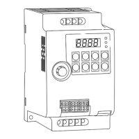
SKI650 Series
- 20 -
The SKI650 solar pump
inverter
must be installed into a control box which has a
tight enclosure to avoid direct sunshine, rain, dust, moisture, animals, plants, etc.
The control box should have a bottom gland plate for installing wire cord or
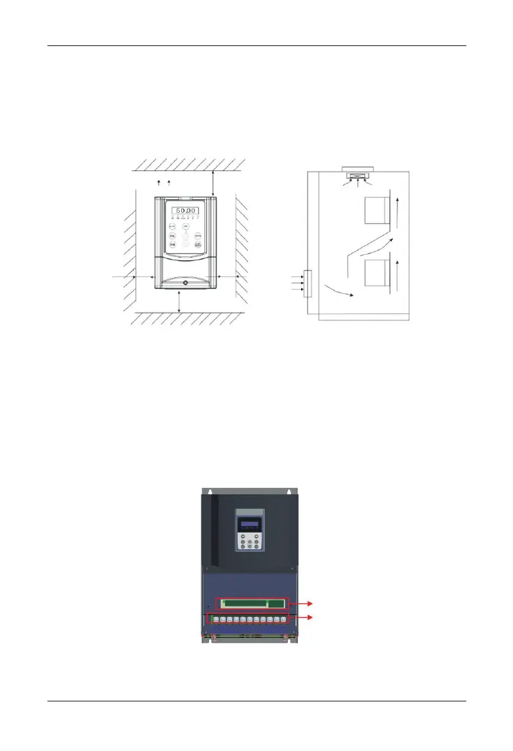
conduit. To decide the size of control box, Please refer to the following Figure 4.
Figure 4 Ventilation Arrangement and Required Distances
3.2 Electrical Installation
3.2.1 Terminals
The following are typical figures of terminal blocks.
Note: Terminals are different in shapes and combinations, depending on different sizes
of
SKI650
Solar Controllers.
Figure 5 Terminals Arrangement of
SKI650
Solar Pump Inverter
100mm
or above
100mm
or above
50mm or above
Ventilation
Dust Filter
Hot Air Ventilation
A
i
r
F
l
o
w
PDS Solar
Pump
Controller
PDS Solar
Pump
Controller
Main
Terminals
Control
Terminals


 To Next Page