EN | 23MCB_miniMCB v2019.1
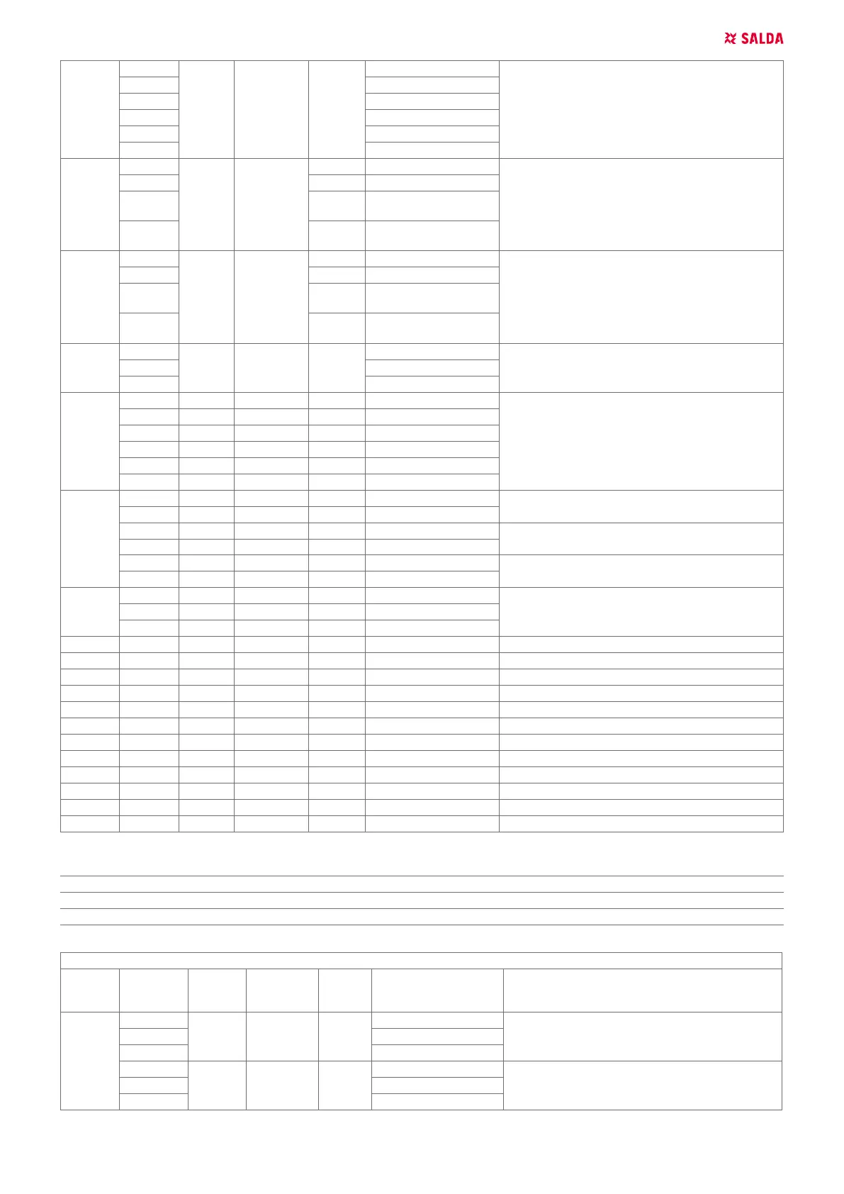
X9
1 PE
Remote Control connection (RS485)
2 GND
3 +24VDC
4 GND
5 RS485_B
6 RS485_A
X10
1 MCB PE
Recirculation damper control 3P
2 MCB GND
3 LED11
MCB RECIRC_+-
24VDC_OPEN (DO4)
4 LED12
MCB RECIRC_+-
24VDC_CLOSE (DO5)
X11
1 MCB PE
By-pass damper control 3P
2 MCB GND
3 LED9
MCB BYPASS_+-
24VDC_OPEN (DO2)
4 LED10
MCB BYPASS_+-
24VDC_CLOSE (DO3)
X12
1 PE
24VDC Power supply for water heater actuator2 GND
3 +24VDC
X13
1 +24VDC
By-pass step motor control
2 STEP_B/
3 STEP_B
4 STEP_A/
5 STEP_A
6 +24VDC
X14
1 GND
Supply air fan control output (0-10VDC)
2 MCB AO1(0-10VDC)
3 GND
Extract air fan control output (0-10VDC)
4 MCB AO2(0-10VDC)
5 GND
Supply air heater control output (0-10VDC)
6 MCB AO3(0-10VDC)
X15
1 +24VDC
MCB Power supply 24VDC2 GND
3 PE
X18 Remote Control connection (RS485)
X19 BMS connection (RS485, congurable via SL1)
F1 1/1 MCB protection MCB power supply fuse
F2 1/1 MCB protection MCB peripheral power fuse
LED1 12V peripheral power indication
LED2 3.3V peripheral power indication
LED3 MCB status LED
LED4 Remote Control (RS485) connection transmit indication
LED5 Remote Control (RS485) connection receive indication
LED6 BMS (RS422/485) connection receive indication
LED7 BMS (RS422/485) connection transmit indication
LED8 Peripheral power control relay indication
SL1 DIP SWITCH PURPOSE (ON POSITION)
1 120R line termination resistor
2 1kR connection line pull-up resistor
3 1kR connection line pull-down resistor
MCB EX1
CONEC-
TION
NO.
CONTACT
NO.
FUSE
NO.
MAX
CURRENT,
A
LED
NO.
CONTACT NAME FUNCTIONAL UNIT TITLE
X20
1 +24VDC
24VDC Power supply for water preheater actuator2 GND
3 PE
4 +24VDC
24VDC Power supply for water cooler actuator5 GND
6 PE