4 | EN MCB_miniMCB v2019.1
2. GENERAL
This manual, dedicated to qualied ventilation or electronics specialists, describes functions, conguration and installation of MCB, MiniMCB
boards to be mounted into air handling units (AHU).
MCB control board consists of the following
› controller MCB (MCB) + controller MCB (EX1)+ controller MCB (EX2).
The MCB control board to be mounted to SMARTY 2RV/2RV plus consists of the following
› controller MCB (REV_C).
MiniMCB control board consists of the following
› controller MiniMCB (main)+ controller MiniMCB (EX1).
MiniMCB control board in addition to pressure switch consists of the following
› controller MiniMCB (main)+ controller MiniMCB (EX1 excl. pressure switches).
MiniMCB basic control board consists of the following
› controller MiniMCB (main).
3. SAFETY INSTRUCTIONS AND ALARMS
Prior to installation and use of the unit, please read this Manual carefully. Installation, connection and maintenance shall be executed by a qualied
specialist considering the local rules, normative acts and practice.
Prior to connecting peripherals to the board, please read the Manual.
The Company shall not assume any liability for personal injuries or damage to property in case of failure to observe these safety requirements, if
the product is modied without manufacturer’s consent
3.1. DANGER
Prior to execution of any electrical or maintenance works make sure the product is disconnected from power supply network.
› Upon noticing any liquid on electrical, energized parts or joints, terminate operation of the device.
› Do not plug the unit to any power outlet except to the one indicated on the label on the casing of the unit.
› The unit mains voltage must comply with the electrotechnical parameters indicated in the label.
Based on the Rules for Installation of Electrical Facilities the product shall be grounded. It is forbidden to plug in and operate it non-grounded.
3.2. ALARMS
Electrical power switching and unit maintenance shall be performed only by qualied employee following the manufacturer manual and applicable
safety instructions.
› To reduce a potential risk during maintenance or installation works appropriate safety clothes shall be worn.
› Electrical power to power mains must be connected via appropriate rating circuit-breaker.
4. TRANSPORTATION AND STORAGE RULES
Automation boards MCB, mini MCB produced by Salda UAB shall be transported and stored by following the following rules:
› Components on the boards are easily vulnerable, therefore it is necessary to protect them against mechanical impact – shocks, crushing,
compression, etc.;
› The boards shall be transported only in rigid cardboard package, wrapped into anti-static bubble lm, protecting against mechanical impact;
› Storage temperature shall be 5-40 °C;
› Storage relative humidity – <70 %; non-condensing;
› It is necessary to avoid entrance of dust and other foreign matter on the boards;
› Only packed boards shall be stored;
› Package shall be protected against direct sunlight;
› After the automation boards are unpacked, they shall be checked for damage during transportation. It is forbidden to install damaged units!!!
› Upon unloading and warehousing the automation boards use the appropriate hoisting equipment to avoid damage and injuries. The units
must not be lifted by holding them by the power cords, connection boxes and automation components.
5. FUNCTIONAL DESCRIPTION
The software installed in the control board includes all the functions indicated in this section, however the unit operation and control depends on
the following:
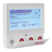
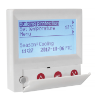
› Selected remote control panel - all functionality and possibility of conguration is ensured only by MB-Gateway web interface;
› Connected accessories: heaters, dampers, transmitters, etc. (refer to description of purchased ventilation system);
› Internal unit components: heat exchanger type (plate or rotary one), integrated dampers, transmitters, etc. (Refer to section about the se-
lected product components);
› Type of control board - dierent boards enable connection of other type components (refer to product board diagram).
5.1. SYSTEM MODES
› Stand-by;
› Building protection;
› Economy;
› Comfort.