12 | EN STOUCH v2019.1
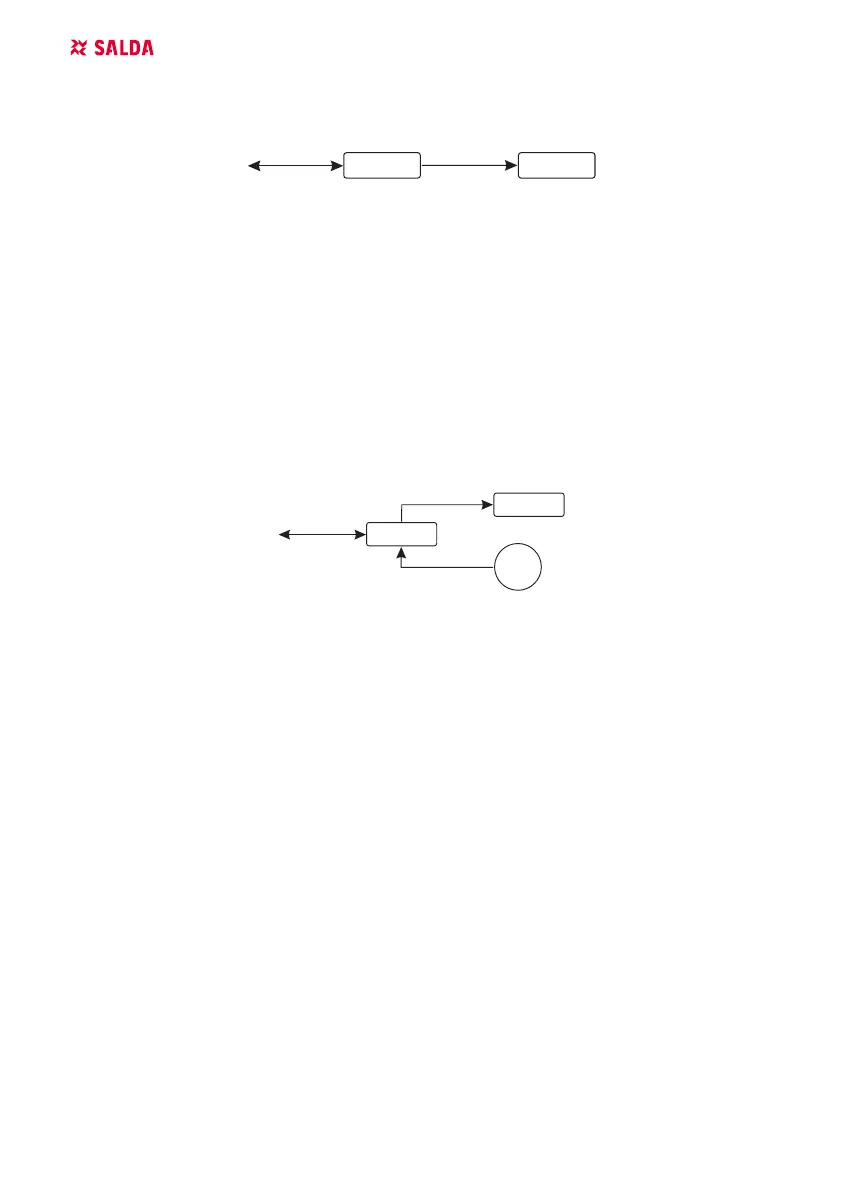
12.3. FAN CONTROL WHEN SPEED IS SET USING CONTROLLER AND/
OR COMPUTER VIA MODBUS
0...10 VDC
RC
FAN
MODBUS
0...10 VDC
RC
FAN
MODBUS
0...10 VDC
PS
0...10 VDC
RC
FAN
0...10 VDC
PS
MODBUS
AHU
MODBUS
RC
AHU
RC
AHU
BMS
RC - controller (master); FAN - fan
Using this remote controller and CO
2
transmitter it is possible to reduce inside carbon dioxide level.
This controller allows controlling both device and 0..10 VDC fan. In service menu, select desired
speed control method (F.01). If control based on preset speeds is selected, then select them in menu
items F.03, F.04, F.05, F.06.
NOTE: The air quality converters and remote controller (when fan is controlled) must be powered
from a separate power source. It is not supplied with the remote.
12.4. PRESSURE CONTROL WHEN SELECTED USING CONTROLLER
AND/OR COMPUTER VIA MODBUS
MODBUS
RC
AHU
0...10 VDC
RC
FAN
MODBUS
0...10 VDC
RC
FAN
MODBUS
0...10 VDC
PS
0...10 VDC
RC
FAN
0...10 VDC
PS
MODBUS
AHU
MODBUS
RC
AHU
RC
AHU
BMS
RC - controller (master); PS - pressure sensor; FAN - fan
Desired pressure can be maintained by connecting 0..10 VDC fan and 0..10 VDC pressure convert-
er directly to the controller. Control and pressure sensor parameters can be changed in controller.
When controller is used as Modbus slave device (air handling unit is not controlled by this principle),
it allows controlling all parameters and monitoring of pressure sensor readings.
For pressure based control, select the following parameters in the service menu:
F.01 - 2
F.14 - 1
F.15 and F.16 - based on pressure converter parameters
F.11, F.12 and F.13 - (PID control ratios). If pressure is maintained incorrectly, these parameters
can be adjusted.
F.0 - F.10 - seting of xed speeds (supports dierent pressure level in Pa)
F.43 -1 - 0..10VDC output activated.