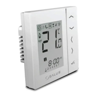
73 VS20WRF and VS20BRF Installer Manual
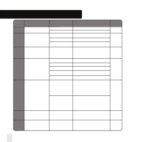
Installation - Device Parameters
D01 Heating 0 Pulse Width Modulation
Control 1* On-Off 0.5 Deg C +/- 0.25 Deg C 0
2 On-Off 1.0 Deg C +/- 0.5 Deg C
D02 Room -3.0 to 3.0 Temperature Offset from
Temperature Deg C Measured Temperature to 0 Deg C
Offset Compensate for any error
D03 Sensor probe or 0 Sensor/Cyl stat not Connected
Cylinder thermostat 1 Sensor/Cyl stat Connected
connection 2 DEW point sensor connected 0
0 Cylinder probe not connected
1 Cylinder probe connected
D04 Sensor probe 0 D03 must be set to 1 then
used as air sensor external sensor be used as
or floor sensor Air sensor. There will be no
internal temp measurement
0
1 D03 must be set to 1 then
external sensor used for floor
protection. Internal temp is
measured by stat
D05 Cooling Control 1 On-Off 0.5 Deg C +/- 0.25 Deg C
2
2 On-Off 1.0 Deg C +/- 0.5 Deg C
D06 Actuator type 0 NO Normally Open
1
1 NC Normally Closed
* When thermostat is paired with TRV then D01 default will be “1”
DX
FUNCTION
SYSTEM SETTING
DEFINITION
DEFAULT
D00
Temperature display
0
1
Temperature display in C
Temperature display in F
0