Index revision : C 8 6209
3.5.1. Analog input
Cabling on external adjustment points can be 4/20 mA or 0-10 V.
3.5.1.1. 4/20 mA adjustment point
This scale setting has to be done in a PLC. To do this, apply an adjustment point of 8 mA and another
adjustment point of 16 mA and read the HV value on the
GNM
screen. A simple calculation permits one
to fine the corresponding point.
3.5.1.2. 0/10 V adjustment point
Scale setting is done inside the
GNM
.
10 V corresponds to 100
kV
. For a high voltage unit on which the maximum voltage is below 100
kV
, the
adjustment point is automatically reveled at its maximum value.
3.5.2. Control of
Vm
and Im outputs
Copies of
Vm
and Im are only given as indications. They are not calibrated inside the
GNM
and differ-
ences can exist.
3.5.2.1. Control of the
Vm
output
The
Vm
scale is 0-5 V for 0-100
kV
. The minimum impedance of the measure equipment has to be 50
k
Ω
.
3.5.2.2. Control of the Im output
The Im scale is 0-5 V for 0-500 µA.
The minimum impedance of the measure equipment has to be 50 k
Ω
.
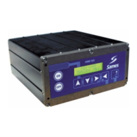
3.5.3. Wiring of external trigger
Control of the external trigger can be done in two ways:
• Dry contact,
• Using external voltage between 12 and 24 Vdc (see § 3.5.3.2 page 9).
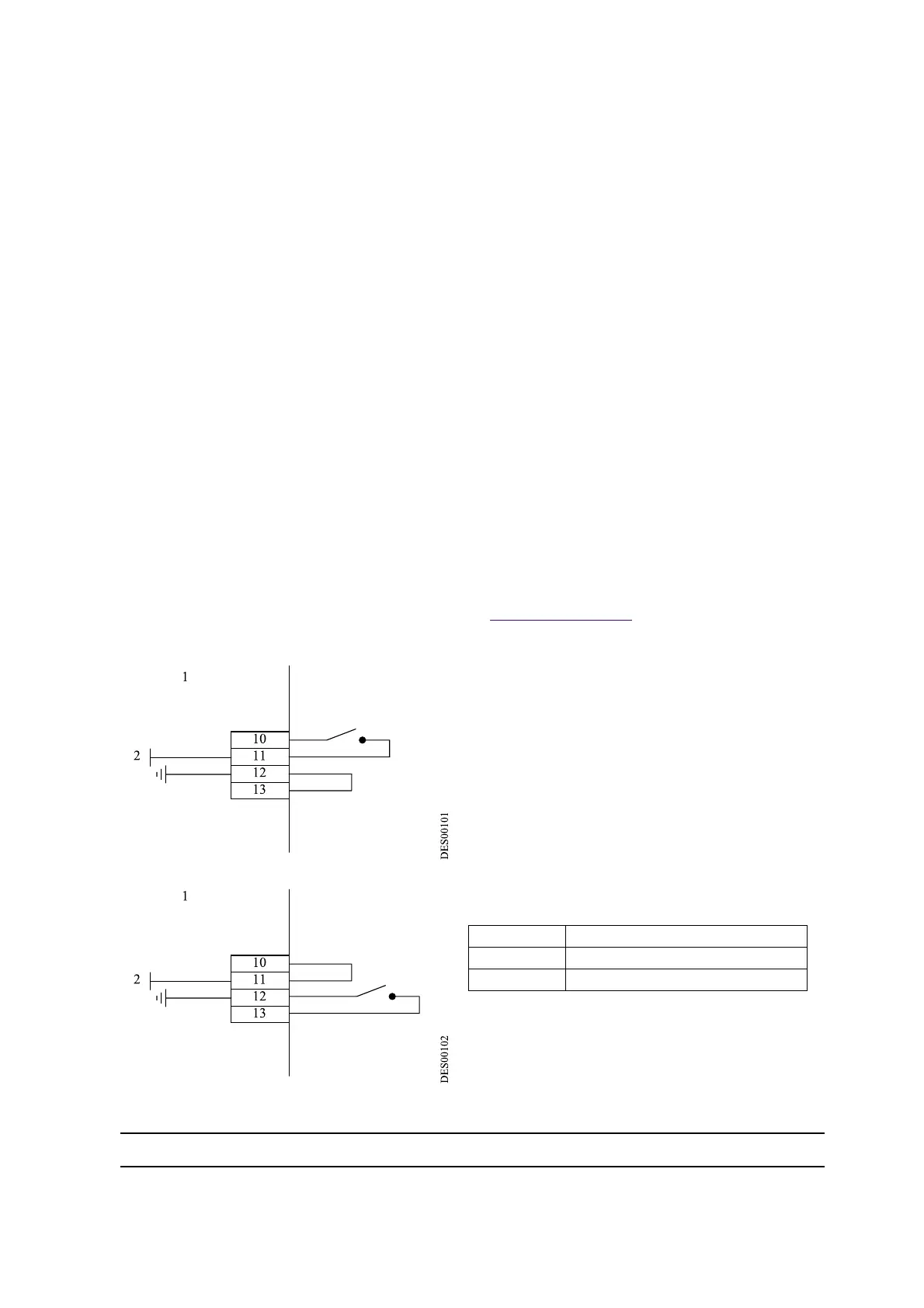
3.5.3.1. Dry contact. There are two possibilities:
or :
1 Inside
GNM
2 + 15 Vdc; 50 mA max
10 to 13
GNM
case