2. CONTROLS, INDICATORS AND CONNECTORS
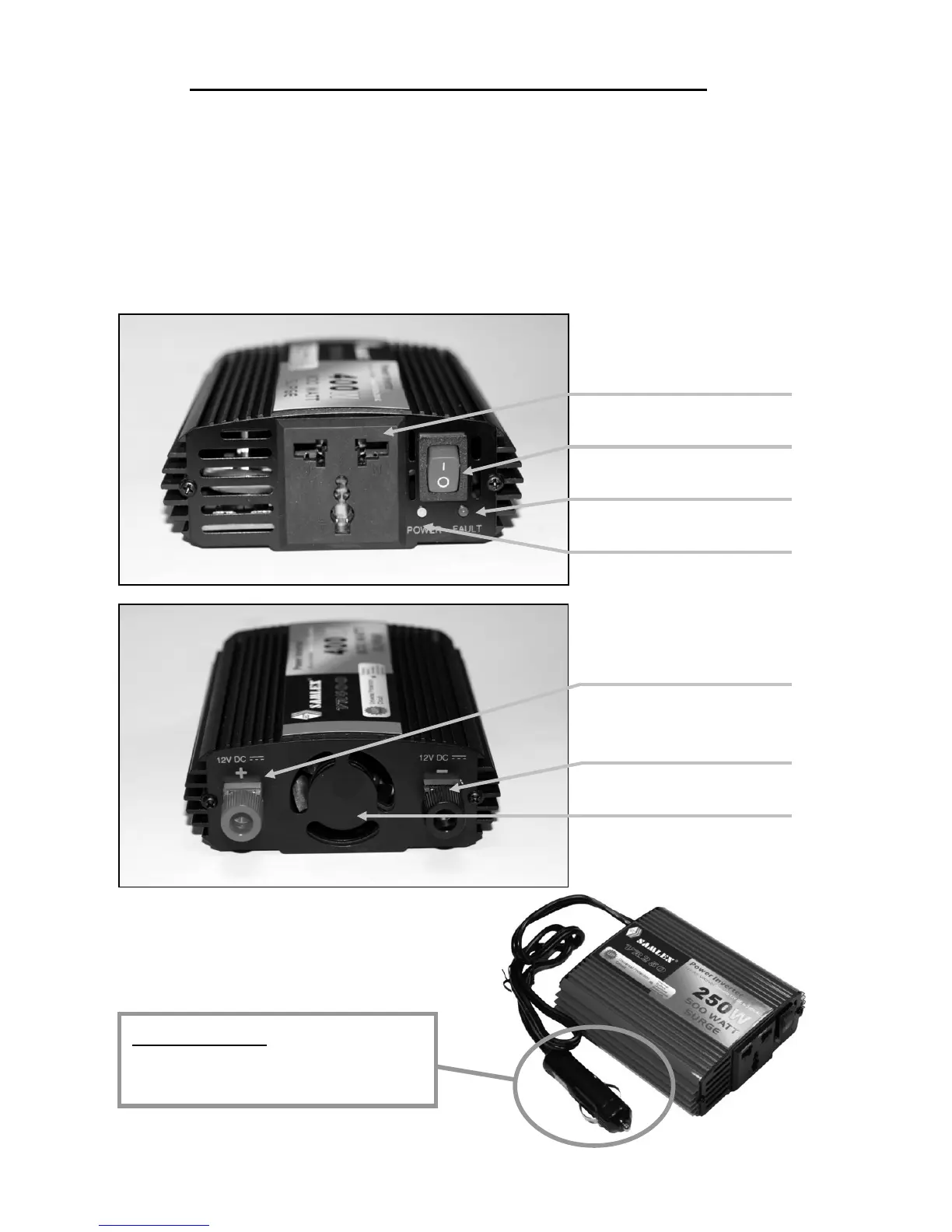
Figure 1 & 2 detail the front & back panel of the inverter. The front panel
provides two LED indicators. A green LED shows proper operation when lit.
The red LED shows inverter shutdown from overload, over voltage or over
temperature. Power is supplied through one worldwide universal outlet. The
outlet accommodates either two or three pin AC plugs. An ON/OFF switch
turns the inverter circuitry ON and OFF. The switch is used to force reset of
inverter circuits if it is switched OFF, then ON.
ONE Universal AC Outlet
ON/OFF SWITCH
Red LED ÆFAULT
Green LED ÆPOWER
(+) DC Power Connection
[400W Only]
(-) DC Power Connection
[400W Only]
Turbo Cooling Fan
FIGURE 1:
FIGURE 2:
12V DC PLUG
Parts for 175W & 250W
O