8
Expedition EX20
Guided Tour
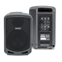
1: Input connector - Use this balanced female XLR connector to route
line-level signal into the EX20.
2: Output VU meter - This three-segment bar meter shows the EX20
output level. For optimum signal-to-noise ratio, set the Volume control
(see #6 below) so that program material is usually at or around 0 VU, with
occasional but not steady excursions to the red “+3 dB” segment.
3: Power switch - Use this to turn power to the EX20 on or off.
4: Voltage selector - Make sure this is set correctly for the country you are
in before turning on the power to the EX20.
5: Battery VU meter - If an optional RB 2030 rechargable battery pack is
installed, this meter shows how much battery power remains as it is being
charged (Power switch off) or depleted (Power switch on).
6: Volume control - This knob sets the level of the EX20’s built-in power
amplifiers.
7: Output connector- This balanced male XLR connector carries line-level
output signal from the EX20. It is used to send signal to a second EX20
being daisy-chained (see interconnection diagram on the following page)
or to an optional EX500 subwoofer.
8: Limiter switch - Use this switch to turn the built-in limiter circuitry on or
off. In order to maximize speaker protection, we recommend that this
switch be left in the “on” position during normal operation.
9: AC output - A standard AC power outlet.
10: AC input - Connect the supplied heavy-gauge 3-pin “IEC” power cable
here.
Interconnecting the EX20