ENGLISH
FRANÇAISDEUTSCHEESPAÑOLITALIANO
7
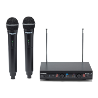
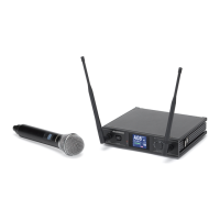
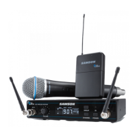
Stage v266: Dual Handheld Wireless
1. Power Switch - Press to turn
the receiver on or o.
2. Power Indicator - Lights red
when the receiver is powered
on.
3. Volume Control (Channel 1) - Rotate to adjust the level of the audio signal output from the
Channel 1 receiver.
4. Channel 1 RF Indicator - Lights green when the corresponding Channel 1 HT6 transmitter is
powered on, and there is an RF signal present and detected by the receiver.
5. Volume Control (Channel 2) - Rotate to adjust the level of the audio signal output from the
Channel 2 receiver.
6. Channel 2 RF Indicator - Lights green when the corresponding Channel 2 HT6 transmitter is
powered on, and there is an RF signal present and detected by the receiver.
7. DC Input - Connect the sup-
plied 12-volt, 200 mA power
adapter here.
WARNING: The substitution
of any other kind of power
adapter can cause severe dam-
age to the SR266 and will void
your warranty.
8. Channel 1 Output - Use this
unbalanced, ¼” jack to connect
the SR266 Channel 1 receiver
to the line level input of a
mixer, amplifier, or other audio
equipment. For a mixed signal
of both receivers, only plug
into one output on the SR266.
Otherwise, Channel 1 and
Channel 2 will output separate
signals.
9. Channel 2 Output - Use this unbalanced, ¼” jack to connect the SR266 Channel 2 receiver to
the line level input of a mixer, amplifier, or other audio equipment. For a mixed signal of both
receivers, only plug into one output on the SR266. Otherwise, Channel 1 and Channel 2 will
output separate signals.
10. Adaptor Strain Relief - Loop the included adaptor’s cord through the
strain relief to prevent the plug from accidentally detaching from the
receiver.
11. Antenna - The antenna mountings allow full rotation for optimum
placement. In normal operation, both antennas should be placed in a vertical position. The
antennas can be folded inward for convenience when transporting the SR266.
SR266 Receiver Controls and Features
9 8 10
7 1111