16-26 EB 5573 EN
Appendix A (conguration instructions)
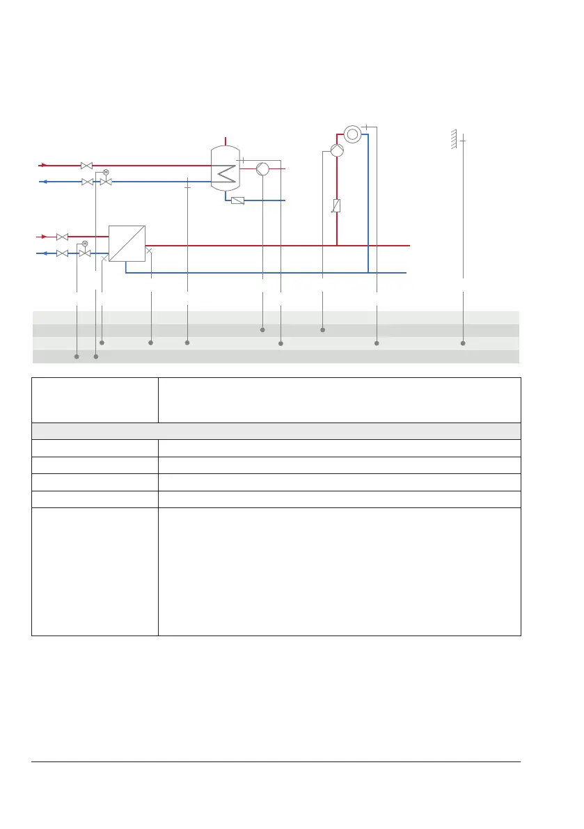
System Anl 11.5
BE
BA
AE
RK1 RüF1
VF1 UP1 AF1
RF1
WW
KW
ZP
RüF2
SF1
RK2
Note: DHW circuit with adjustable valve position for storage tank charging in ab-
solute priority operation. By using RüF2, the ready-adjusted valve position
issubjecttothereturnowtemperaturelimitation.
Default setting
CO1->F01 - 0 (without RF1)
CO1->F02 - 1 (with AF1)
CO4->F02 - 0 (without SF2)
CO4->F03 - 1 (with RüF2)
CO5'->F10
Functionofthe0to10Voutput:
− 1=ControlsignalRK1
− 2=ControlsignalRK2
− 6=Externaldemand
When
CO1->F18-1
− 5=Outdoortemperature When
CO5->F23-1
Direction 'AA'