EB 5573 EN 16-27
Appendix A (conguration instructions)
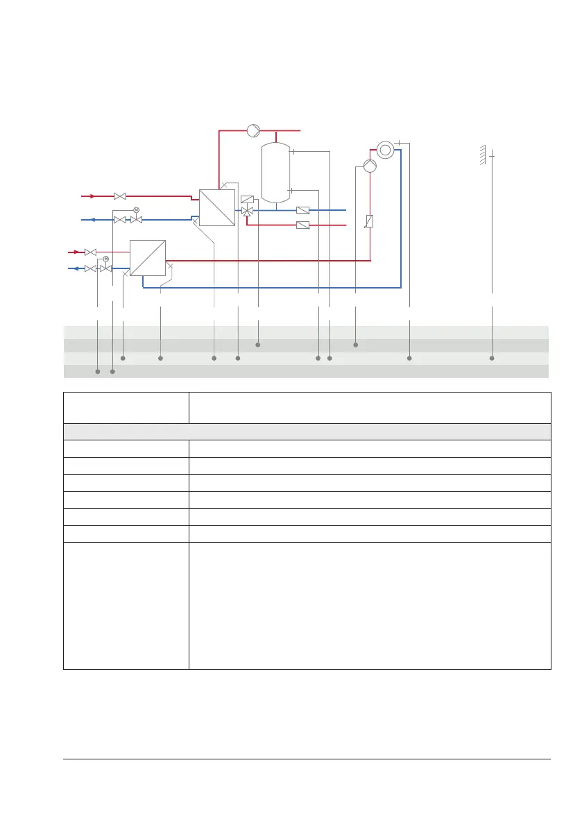
System Anl 11.6
BE
BA
AE
WW
KW
RK2
Z
RK1
VF2VF1 SF2 UP1 AF1
RüF2 SLP/ZP SF1 RF1RüF1
1)
1)
Note: Install a continuously running pump in the DHW circuit and connect it di-
rectly to the supply voltage.
Default setting
CO1->F01 - 0 (without RF1)
CO1->F02 - 1 (with AF1)
CO1->F03 - 1 (with RüF1)
CO4->F01 - 1 (with SF1)
CO4->F02 - 1 (with SF2)
CO4->F03 - 0 (without RüF2)
CO5'->F10
Functionofthe0to10Voutput:
− 1=ControlsignalRK1
− 2=ControlsignalRK2
− 6=Externaldemand
When
CO1->F18-1
− 5=Outdoortemperature When
CO5->F23-1
Direction 'AA'