16-56 EB 5573 EN
Appendix A (conguration instructions)
Parameters Default Switch position: value range
DHW temperature set point or charging
temperaturewithCO4->F01-0setting
60.0°C
: Min. to max. DHW temperature
DHW temperature sustaining value
40.0°C
: Min. to max. DHW temperature
Parameters Default Parameter level: value range
Min.DHWtemperature
1)
40.0°C PA4:5.0to90.0°C
Max.DHWtemperature
1)
60.0°C PA4:5.0to90.0°C
Hysteresis
2)
5.0°C PA4:0.0to30.0°C
Charging temperature boost
3)
10.0°C PA4:0.0to50.0°C
Lag time for storage tank charging pump 1.0 PA4: 0.0 to 10.0
2)
Parameters serve as limitation of the adjustment range for the DHW temperature to be set at the ro-
tary switch
3)
DeactivationvalueT='DHWtemperature'+'Hysteresis'
4)
ChargingtemperatureT='DHWtemperature'+'Chargingtemperatureboost'
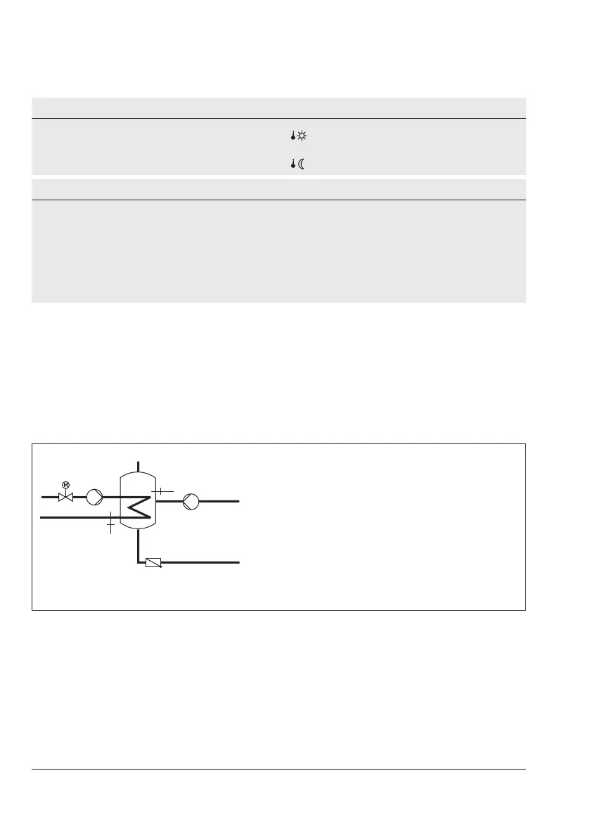
16.3.1.1 DHW circuit additionally controlled by a globe valve
InsystemAnl11.1,thefollowingversionwithglobevalvecanbeconguredinsteadofthe
three-way valve control in the DHW circuit:
KW
SF1
VF2
ZP
SLP
Rk2/Y2
Rk2/Y2 Controlcircuit/valve2
SLP Storage tank charging pump
SF1 Storage tank sensor
VF2 Flow sensor
ZP Circulation pump (DHW)
WW Hot water
KW Cold water
Fig.16-6: Schematics of a storage tank system with a globe valve for return ow temperature
limitation
GlobevalveandowsensorVF2areusedexclusivelyforreturnowtemperaturelimitation
intheschematicsshownabove.Thepre-controlcircuitprovidesatleastthesameowtem-
perature as in the standard schematic version which is calculated from 'DHW temperature set
point'+'Chargingtemperatureboost'+'Boostsetpointofpre-controlcircuit'.
The functions and parameters of the DHW heating in the storage tank system are upgraded
by the following settings: