EB 5573 EN 16-57
Appendix A (conguration instructions)
Functions Default Conguration
DHW circuit additionally controlled by a
globe valve
0 CO4->F20-1
Parameters Default Parameter level: value range
Max.returnowtemperature 65.0°C PA4:20.0to90.0°C
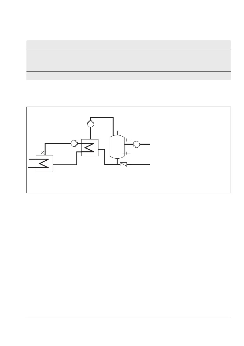
16.3.2 DHW heating in the storage tank charging system
Start storage tank charging
WW
SF1
SF2
SLP
TLP
ZP
KW
VF
TLP Heat exchanger charging
pump
VF Flow sensor
SLP Storage tank charging
pump
SF1 Storage tank sensor
SF2 Storage tank sensor
ZP Circulation pump (DHW)
WW Hot water
KW Cold water
Fig.16-7: Schematics of a storage tank charging system
The controller begins charging the storage tank when the water temperature measured at
sensorSF1fallsbelowthe'DHWtemperaturesetpoint'by0.1°C.Iftheowtemperaturein
thesystemexceedsthedesiredchargingtemperature,thecontrollertriestoreducetheow
temperature in the heating circuit for up to three minutes before the exchanger charging
pump is activated together with the storage tank charging pump.
Whenthereisnoheatingoperationorwhentheowtemperatureinthesystemislower,the
exchanger charging pump is switched on immediately. If the temperature currently measured
at sensor SF1 is reached at the sensor VF, the storage tank charging pump is switched on. An
activatedsettingCO4'->F03-1(dischargingprotection)causesthechargingtobestopped
when the charging temperature does not reach its set point even though the valve is fully
open or it falls below the temperature measured at SF1 and does not rise again. Charging
with the valve fully open is stopped after one hour at the latest.
If a storage tank thermostat is used, the storage tank charging pump is switched on as soon
asthetemperatureT='Chargingtemperature'–5°CisreachedatthesensorVF.