EB 5573 EN 16-77
Appendix A (conguration instructions)
16.5 Communication
Using the optional RS-485 communication
module (Modbus RTU interface for two-
wirebusnetworks),theTROVIS5573
Heating Controller can communicate with
a control system. In combination with a
suitable software for process visualization
and communication, a complete control
system can be implemented.
The operating software can be updated
over a data cable, provided Modbus has
been activated (CO6->F01-1).
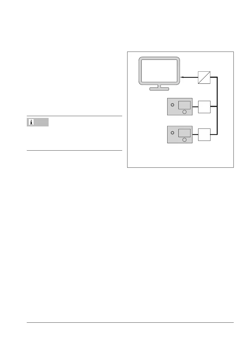
RS-232
RS-485
RS-232C
TROVIS 5573
RS-485
1
1
GLT
1: Optional RS-485 communication module
Fig.16-9: Network structure
16.5.1 RS-485 communication module
When looking onto the controller front, the connection for the optional communication mod-
ule (icon, order no. 8812-2002) is located on the left side of the controller housing (RJ-45
connectorsocket).Thebuslinelinksthecontrolunits/devicesinanopenring.Attheendof
the bus line, the data cable is connected to the control station using an RS-485 to RS-232
converter (e.g. CoRe02).
The maximum range of the bus connection (cable length) is 1200 meters. For greater distanc-
es, repeaters (e.g. CoRe02) must be used to regenerate the signal level. A maximum of 246
devices with 8-bit addressing can be connected to a bus.
If no communication is established between the control system and controller, the time of ac-
cess by the control system can be restricted to dynamic process by the monitoring function.
The controller resets the monitoring function, provided the valid Modbus requests are regis-
tered. However, in case of an error, all level bits are initialized back to “autonomous” after
30 minutes have elapsed.
Note