12
Installation Procedure
English
Installation Procedure
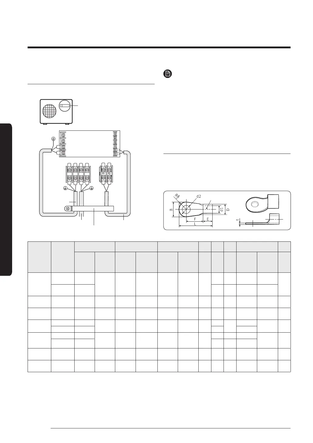
Connecting the outdoor-to-indoor power cable
and the communication cable
For connecting the power and
communication cables
1(L) 2(N)
N
L
Indoor Unit
Main power cable
Cable clamp
Outdoor-to-
indoor power
cable
Communication cable
1(L)
F2
F1
2(N)
NOTE
• Lay the electrical wiring so that the front cover does
not rise up when doing wiring work and attach the
front cover securely.
• Ground wire for the indoor unit and outdoor unit
connection cable must be clamped to a soft copper
tin-plated eyelet terminal with M4 screw hole(NOT
SUPPLIED WITH UNIT ACCESSORIES).
Outdoor-to-indoor power terminal
specifications
• Connect the cables to the terminal board using the
compressed ring terminal.
• Cover a solderless ring terminal and a connector part
of the power cable and then connect it.
Nominal
dimensions
for cable
(mm²)
Nominal
dimensions
for screw
(mm)
B D d1 E F L d2 t
Standard
dimension
(mm)
Allowance
(mm)
Standard
dimension
(mm)
Allowance
(mm)
Standard
dimension
(mm)
Allowance
(mm)
Min.
(mm)
Min.
(mm)
Max.
(mm)
Standard
dimension
(mm)
Allowance
(mm)
Min.
(mm)
4/6
4 9.5
±0.2 5.6
+0.3
-0.2
3.4 ±0.2 6
5 20 4.3
+0.2
0
0.9
8 15 9 28.5 8.4
+0.4
0
10 8 15 ±0.2 7.1
+0.3
-0.2
4.5 ±0.2 7.9 9 30 8.4
+0.4
0
1.15
16 8 16 ±0.2 9
+0.3
-0.2
5.8 ±0.2 9.5 13 33 8.4
+0.4
0
1.45
25
8 12
±0.3 11.5
+0.5
-0.2
7.7 ±0.2 11
15
34
8.4
+0.4
0
1.7
8 16.5 13 8.4
35
8 16
±0.3 13.3
+0.5
-0.2
9.4 ±0.2 12.5
13 38 8.4
+0.4
0
1.8
8 22 13 43 8.4
50 8 22 ±0.3 13.5
+0.5
-0.2
11.4 ±0.3 17.5 14 50 8.4
+ 0.4
0
1.8
70 8 24 ±0.4 17.5
+0.5
-0.4
13.3 ±0.4 18.5 20 51 8.4
+ 0.4
0
2.0
• Connect the rated cables only.
• Connect using a driver which is able to apply the rated torque to the screws.
• If the terminal is loose, fire may occur caused by arc. If the terminal is connected too firmly, the terminal may be
damaged.
 Loading...