22
Installation Procedure
English
Installation Procedure
026/035
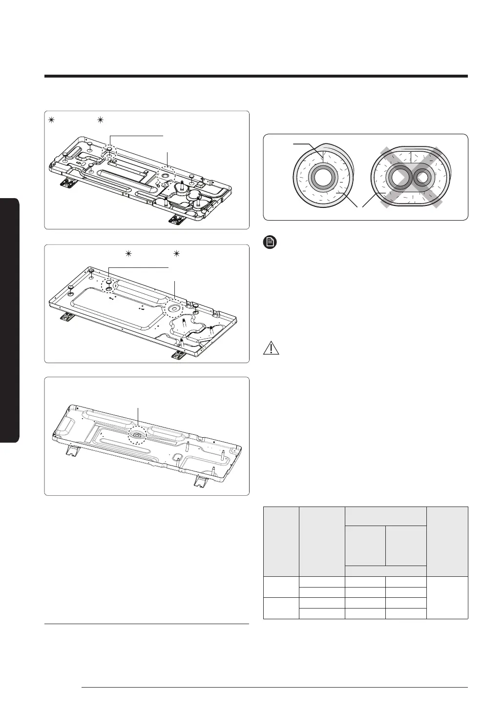
Drain cap (5EA)
Drain plug (1EA)
/AC052MXASEH
060/071
Drain cap (4EA)
Drain plug (1EA)
AC052MXADKH/
AC100MXASEH
Drain plug (1EA)
• When installing the product, make sure that the
rack is not placed under the drain hole.
• If the product is installed in a region of heavy
snow, allow enough separation distance between
the product and the ground.
Step 12 Insulating the refrigerant
pipes
Once you have checked that there are no leaks in the
system, you can insulate the piping and hose.
1 To avoid condensation problems, place an insulator
around each refrigerant pipe.
NOTE
• When insulate the pipe, be sure to overlap the
insulation.
• The insulation has to be produced in full compliance
of European regulation reg. EEC / EU 2037/ 2000
that requires the use of sheaths insulation form
without using CFC and HCFC gases for health and the
environment.
CAUTION
• When insulating the pipe, use non-slit insulator.
2 Select the insulation of the refrigerant pipe.
• Insulate the gas side and liquid side pipe referring
to the thickness according to the pipe size.
• Less than Indoor temperature of 30°C and
humidity of 85% is the standard condition. If
installing in a high humidity condition, use one
grade thicker insulator by referring to the table
below. If installing in an unfavourable conditions,
use thicker one.
• Insulator’s heat-resistance temperature should be
more than 120°C.
Pipe Pipe size
Insulation Type
(Heating/Cooling)
Remarks
Standard
[Less than
30°C, 85%]
High
humidity
[over 30°C,
85%]
EPDM, NBR
Liquid pipe
Ø6.35~Ø9.52 9 t 9 t
Internal
temperature
is higher than
120°C
Ø12.7~Ø19.05 13 t 13 t
Gas pipe
Ø6.35 13 t 19 t
Ø9.52~Ø19.05 19 t 25 t
• When installing insulation in places and conditions
below, use the same insulation that is used for
 Loading...