16
Installation Procedure
English
Installation Procedure
• Temper grade and minimum thickness of the
refrigerant pipe
Outer diameter
[mm]
Minimum
thickness [mm]
Temper grade
ø6.35 0.7
C1220T-O
ø9.52 0.7
ø12.70 0.8
ø15.88 1.0
ø15.88 0.8
C1220T-1/2H OR
C1220T-H
ø19.05 0.9
ø22.23 0.9
CAUTION
• Be sure to use C1220T-1/2H (Semi-hard) pipe for
more than Ø19.05 mm. If you use C1220T-O (Soft)
pipe for Ø19.05 mm, the pipe may be broken, which
can result in an injury.
Make at least one round:
It will reduce noise and vibration
• The appearance of the unit may be different from the
diagram depending on the model.
CAUTION
• After connecting the pipes with knock-out treatment,
plug the space around the pipes.
• After connecting the pipes, proceed exactly as
directed in the guide to prevent interference with the
internal parts.
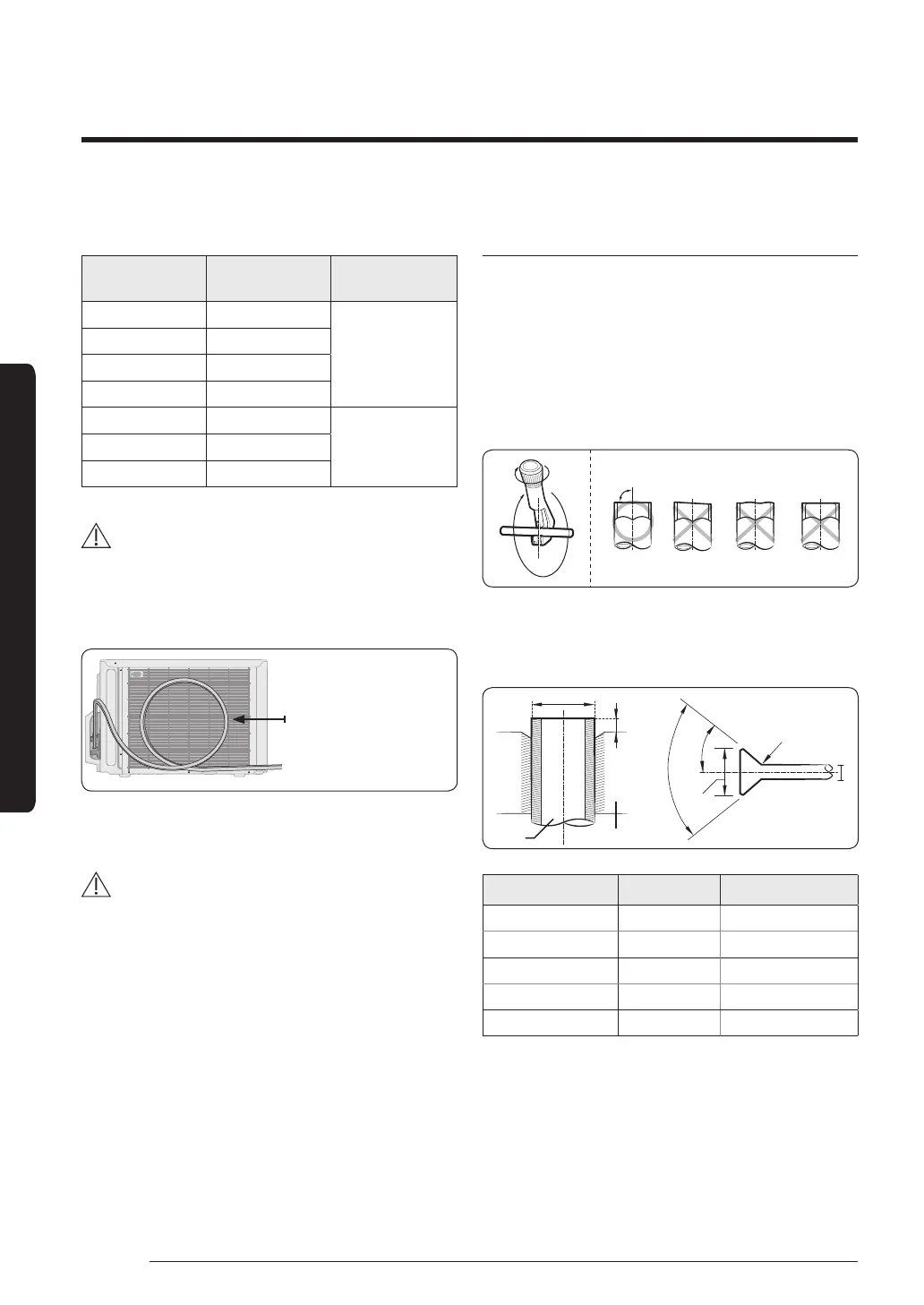
Step 6 Optional: Cutting and aring the
pipes
1 Make sure that you have the required tools available.
(pipe cutter, reamer, flaring tool, and pipe holder)
2 If you wish to shorten the pipes, cut it with a pipe
cutter, taking care to ensure that the cut edge remains
at a 90° angle with the side of the pipe. Refer to
the illustrations below for examples of edges cut
correctly and incorrectly.
3 To prevent any gas from leaking out, remove all burrs
at the cut edge of the pipe, using a reamer.
4 Slide a flare nut on to the pipe and modify the flare.
D
A
D
45° ±2°
90° ±2°
Pipe
Flare
Flare
R 0.4 to 0.8 mm
L
Outer diameter (D) Depth (A) Flare dimension (L)
ø6.35 mm 14 to 18 8.7 to 9.1 mm
ø9.52 mm 34 to 42 12.8 to 13.2 mm
ø12.70 mm 49 to 61 16.2 to 16.6 mm
ø15.88 mm 68 to 82 19.3 to 19.7 mm
ø19.05 mm 100 to 120 23.6 to 24.0 mm
• 1 N·m = 10 kgf·cm
5 Check that the flaring is correct, referring to the
illustrations below for examples of incorrect flaring.
 Loading...