18
Installation Procedure
English
Installation Procedure
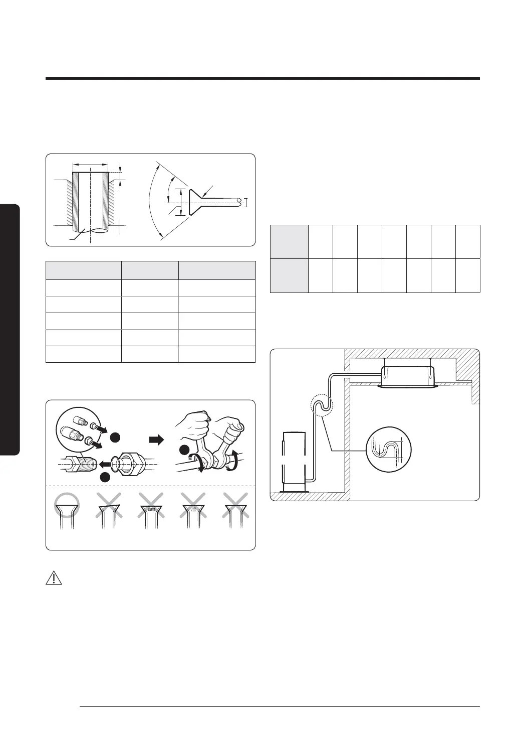
3 To prevent any gas from leaking out, remove all burrs
at the cut edge of the pipe, using a reamer.
4 ƊʒʪɇѤɇθʪЇϩͱϩͱϩ˵ʪΧΧʪɇʒͱʒ˙цϩ˵ʪѤɇθʪ
D
Flare
Flare
L
R 0.4 to 0.8 mm
90° ±2°
45° ±2°
D
Pipe
Outer diameter (D) Depth (A) Flare dimension (L)
ø 6.35 mm 1.3 mm 8.7 to 9.1 mm
ø 9.52 mm 1.8 mm 12.8 to 13.2 mm
ø 12.70 mm 2.0 mm 16.2 to 16.6 mm
ø 15.88 mm 2.2 mm 19.3 to 19.7 mm
ø 19.05 mm 2.2 mm 23.6 to 24.0 mm
5 A˵ʪʀϩ˵ɇϩϩ˵ʪѤɇθ˝ϑʀͱθθʪʀϩࡥθʪ˙ʪθθ˝ϩͱϩ˵ʪ
Їϑϩθɇϩͱϑɵʪͱи˙ͱθʪуɇΧʪϑͱ˙ʀͱθθʪʀϩѤɇθ˝
ߣ
ߤ
ߥ
Correct Inclined Damaged
Surface
Cracked Uneven
Thickness
CAUTION
• If the pipes require brazing ensure that OFN(Oxygen
Free Nitrogen) is flowing through the system.
• Nitrogen blowing pressure range is 0.02 to 0.05 MPa.
Step 7 Installing oil traps
Check the following list and install an oil trap.
• Based on cooling operation, install it on the gas side
pipe only.
• Install the oil trap only in between the outdoor unit
and the first branch joint and it should be installed at
every 10 m.
• Radius of curvature (R) on the oil trap are as follows;
Pipe
diameter
(D, mm)
12.70 15.88 19.05 22.23 25.40 28.60 31.75
Radius of
curvature
(R, mm)
25 and
over
32 and
over
38 and
over
41 and
over
51 and
over
57 and
over
60 and
over
• ²ʪ˝˵ϩͱ˙ϩ˵ʪͱϩθɇΧ࣑²࣒ࡤߦŵ²ߨŵ
• When the indoor unit is installed at a higher place than
the outdoor unit
Indoor Unit
Outdoor Unit
Oil trap (Install it at
every 10 m)
 Loading...