23
English
Installation Procedure
<Operation purpose condition>
– Restaurant ceiling, sauna, swimming pool etc.
– <Building construction condition>
– The ceiling frequently exposed to moisture and
cooling is not covered.
– e.g. The pipe installed at a corridor of a
dormitory and studio or near an exit that opens
and closes frequently.
– The place where the pipe is installed is highly
humid due to the lack of ventilation system.
Step 13 Checking the earthing
If the power distribution circuit does not have a earthing
ͱθϩ˵ʪʪɇθϩ˵˝ʒͱʪϑͱϩʀͱΧциϩ˵ϑΧʪʀѣʀɇϩͱϑࡥɇ
earthing electrode must be installed. The corresponding
accessories are not supplied with the air conditioner.
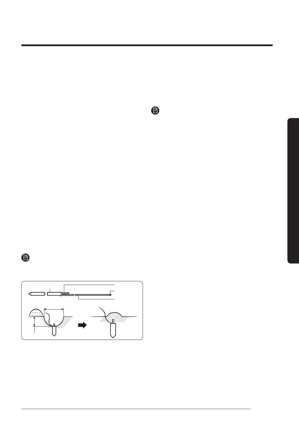
1 Select an earthing electrode that complies with the
ϑΧʪʀѣʀɇϩͱϑ˝Эʪϩ˵ʪЇϑϩθɇϩͱ
2 Aͱʪʀϩϩ˵ʪѤʪуɵʪ˵ͱϑʪϩͱϩ˵ʪѤʪуɵʪ˵ͱϑʪΧͱθϩ
• In damp hard soil rather than loose sandy or gravel
soil that has a higher earthing resistance.
• Away from underground structures or facilities,
such as gas pipes, water pipes, telephone lines and
underground cables.
• At least two metres away from a lightening
conductor earthing electrode and its cable.
NOTE
• The earthing wire for the telephone line cannot be
used to ground the air conditioner.
Carbon plastic
30 cm
50 cm
To grounding screw
Steel core
Terminal M4
PVC-insulated
green/yellow
wire
3 Finish wrapping insulating tape around the rest of the
pipes leading to the outdoor unit.
4 Install a green/yellow coloured earthing wire:
• If the earthing wire is too short, connect an
extension lead in a mechanical way and wrap it with
insulating tape (do not bury the connection).
• Secure the earthing wire in position with staples.
NOTE
• If the earthing electrode is installed in an area with
heavy traffic, its wire must be connected securely.
5 Carefully check the installation by measuring the
earthing resistance with a earth resistance tester. If
the resistance is above the required level, drive the
electrode deeper into the ground or increase the
number of earthing electrodes.
6 Connect the earthing wire to the electrical component
box inside of the outdoor unit.
Step 14 Performing final check and
trial operation
1 Check the power supply between the outdoor unit and
the auxiliary circuit breaker.
• 1 phase power supply : L, N
• 3 phase power supply : R, S, T, N
2 Check the indoor unit.
a
Check that you have connected the power and
communication cables correctly. (If the power
cable and communication cables one mixed up or
connected incorrectly, the PCB will be damaged.)
b
Check that the thermistor sensor, drain pump/
hose, and display are connected correctly.
 Loading...